My Cart
Your Cart 0

    Your cart is empty.

  • Total (Amount) ₹0.00
Previous year question hub

Transformers - Electrical Machines - Electrical Engineering Previous Year Questions

Practice Transformers - Electrical Machines - Electrical Engineering previous year questions organised from real papers, with year-wise coverage and clear topic navigation.

23Papers
16Years
44Questions
1Topics

Transformers question pattern

Every graph below is calculated only from this selection.

Questions by year

Year-wise coverage for Transformers. Each bar uses a separate theme-derived color.

Difficulty distribution

How the classified questions are distributed by difficulty.

Medium 34 77.3%
Easy 8 18.2%
Hard 2 4.5%
Question type distribution

MCQ, numerical, multiple-select and other formats found in these papers.

MCQ 34 77.3%
Numerical Answer Type (NAT) 10 22.7%

Subject weightage

Top subjects by unique question coverage.

Electrical Engineering
44 Qs

Most asked topics

Top topics across the included previous year papers.

Electrical Machines
44 Qs

Subtopic coverage

Top subtopics inside this exact selection.

Transformers
44 Qs

Paper coverage

Question coverage for the most populated papers. Every active PYP paper remains listed below.

Electrical Engineering (EE) 2024
1 Qs
Electrical Engineering (EE) 2023
1 Qs
Electrical Engineering (EE) 2021
1 Qs
Electrical Engineering (EE) 2020
2 Qs
Electrical Engineering (EE) 2019
2 Qs
Electrical Engineering (EE) 2018
3 Qs
Electrical Engineering (EE) 2017 [Session 1]
1 Qs
Electrical Engineering (EE) 2017 [Session 2]
1 Qs
Electrical Engineering (EE) 2016 [Session 1]
4 Qs
Electrical Engineering (EE) 2016 [Session 2]
2 Qs
Electrical Engineering (EE) 2014 [Session 1]
2 Qs
Electrical Engineering (EE) 2014 [Session 2]
2 Qs
Electrical Engineering (EE) 2014 [Session 3]
2 Qs
Electrical Engineering (EE) 2013 [Session 1]
1 Qs
Electrical Engineering (EE) 2013 [Session 2]
1 Qs
Electrical Engineering (EE) 2013 [Session 3]
1 Qs
Electrical Engineering (EE) 2013 [Session 4]
1 Qs
Electrical Engineering (EE) 2012
1 Qs
Electrical Engineering (EE) 2011
1 Qs
Electrical Engineering (EE) 2010
3 Qs
Electrical Engineering (EE) 2009
5 Qs
Electrical Engineering (EE) 2008
2 Qs
Electrical Engineering (EE) 2007
4 Qs

Included previous year papers

Newest papers appear first. Sort by year, question coverage or name.

PaperYear / sessionQuestions in this viewOpen
Electrical Engineering (EE) 202420241View paper
Electrical Engineering (EE) 202320231View paper
Electrical Engineering (EE) 202120211View paper
Electrical Engineering (EE) 202020202View paper
Electrical Engineering (EE) 201920192View paper
Electrical Engineering (EE) 201820183View paper
Electrical Engineering (EE) 2017 [Session 1]20171View paper
Electrical Engineering (EE) 2017 [Session 2]20171View paper
Electrical Engineering (EE) 2016 [Session 1]20164View paper
Electrical Engineering (EE) 2016 [Session 2]20162View paper
Electrical Engineering (EE) 2014 [Session 1]20142View paper
Electrical Engineering (EE) 2014 [Session 2]20142View paper
Electrical Engineering (EE) 2014 [Session 3]20142View paper
Electrical Engineering (EE) 2013 [Session 1]20131View paper
Electrical Engineering (EE) 2013 [Session 2]20131View paper
Electrical Engineering (EE) 2013 [Session 3]20131View paper
Electrical Engineering (EE) 2013 [Session 4]20131View paper
Electrical Engineering (EE) 201220121View paper
Electrical Engineering (EE) 201120111View paper
Electrical Engineering (EE) 201020103View paper
Electrical Engineering (EE) 200920095View paper
Electrical Engineering (EE) 200820082View paper
Electrical Engineering (EE) 200720074View paper

All Transformers previous year questions

Practice every matching question in batches of 20, with every available option.

1
2007 · Electrical Engineering · Electrical Machines · Transformers
Electrical Engineering (EE) 2007

In a transformer, zero voltage regulation at full load is

Open complete paper
2
2007 · Electrical Engineering · Electrical Machines · Transformers
Electrical Engineering (EE) 2007

A single-phase 50 kVA, 250V/500V two winding transformer has an efficiency of 95% at full load, unity power factor. If it is reconfigured as a 500V/750V autotransformer, its efficiency at its new rated load at unity power factor will be

Open complete paper
3
2007 · Electrical Engineering · Electrical Machines · Transformers
Electrical Engineering (EE) 2007
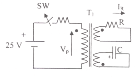
In the figure, transformer T1 has two secondaries, all three windings having the same number of turns and with polarities as indicated. One secondary is shorted by a 10 Ω resistor R, and the other by a 15 μF capacitor. The switch SW is opened (t = 0) when the capacitor is charged to 5 V with the left plate as positive. At t = 0+ the voltage Vp and current IR are

Question diagram

Open complete paper
4
2007 · Electrical Engineering · Electrical Machines · Transformers
Electrical Engineering (EE) 2007
If an autotransformer is used for reduced voltage starting to provide 1.5 per unit starting torque, the autotransformer ratio (%) should be
Open complete paper
5
2008 · Electrical Engineering · Electrical Machines · Transformers
Electrical Engineering (EE) 2008

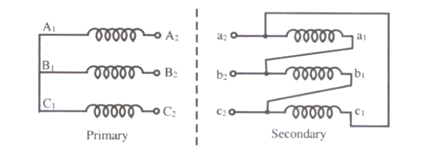
Three single-phase transformers are connected to form a 3-phase transformer bank. The transformers are connected in the following manner:

Question diagram

The transformer connection will be represented by
Open complete paper
6
2008 · Electrical Engineering · Electrical Machines · Transformers
Electrical Engineering (EE) 2008
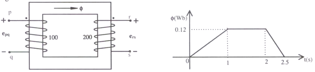
The core of a two-winding transformer is subjected to a magnetic flux variation as indicated in the figure.
The induced emf (\(e_{23}\)) in the secondary winding as a function of time will be of the form

Question diagram

Open complete paper
7
2009 · Electrical Engineering · Electrical Machines · Transformers
Electrical Engineering (EE) 2009
The single phase, 50Hz, iron core transformer in the circuit has both the vertical arms of cross sectional area 20\(cm^2\) and both the horizontal arms of cross sectional area 10\(cm^2\). If the two windings shown were wound instead on opposite horizontal arms, the mutual inductance will
Open complete paper
8
2009 · Electrical Engineering · Electrical Machines · Transformers
Electrical Engineering (EE) 2009
With both S1 and S2 open, the core flux waveform will be
Open complete paper
9
2009 · Electrical Engineering · Electrical Machines · Transformers
Electrical Engineering (EE) 2009
With S2 closed and S1 open, the current waveform in the delta winding will be
Open complete paper
10
2009 · Electrical Engineering · Electrical Machines · Transformers
Electrical Engineering (EE) 2009
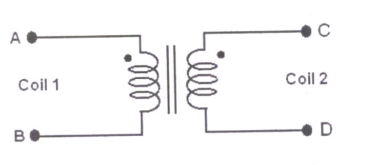
The coils are to be connected to obtain a single phase, 400/1000 V, auto-transformer to drive a load of 10kVA. Which of the options given should be exercised to realize the required auto-transformer?

Question diagram

Open complete paper
11
2009 · Electrical Engineering · Electrical Machines · Transformers
Electrical Engineering (EE) 2009

In the autotransformer obtained in Question 57, the current in each coil is

Open complete paper
12
2010 · Electrical Engineering · Electrical Machines · Transformers
Electrical Engineering (EE) 2010

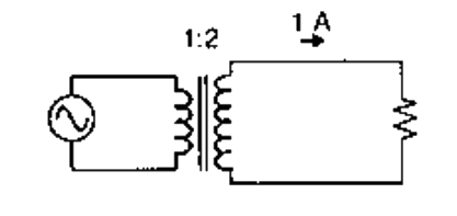
A single-phase transformer has a turns ratio of 1:2, and is connected to a purely resistive load as shown in the figure. The magnetizing current drawn is 1 A, and the secondary current is 1 A. If core losses and leakage reactances are neglected, the primary current is

Question diagram

Open complete paper
13
2010 · Electrical Engineering · Electrical Machines · Transformers
Electrical Engineering (EE) 2010

The zero-sequence circuit of the three phase transformer shown in the figure is

Question diagram

Open complete paper
14
2010 · Electrical Engineering · Electrical Machines · Transformers
Electrical Engineering (EE) 2010
A balanced star-connected and purely resistive load is connected at the secondary of a star-delta transformer as shown in the figure. The line-to-line voltage rating of the transformer is 110 V / 220 V. Neglecting the non-idealities of the transformer, the impedance \(Z\) of the equivalent star-connected load, referred to the primary side of the transformer, is
Open complete paper
15
2011 · Electrical Engineering · Electrical Machines · Transformers
Electrical Engineering (EE) 2011

A single-phase air core transformer, fed from a rated sinusoidal supply, is operating at no load. The steady state magnetizing current drawn by the transformer from the supply will have the waveform

Open complete paper
16
2012 · Electrical Engineering · Electrical Machines · Transformers
Electrical Engineering (EE) 2012

A single phase 10 kVA, 50 Hz transformer with 1 kV primary winding draws 0.5 A and 55 W, at rated voltage and frequency, on no load. A second transformer has a core with all its linear dimensions √2 times the corresponding dimensions of the first transformer. The core material and lamination thickness are the same in both transformers. The primary windings of both the transformers have the same number of turns. If a rated voltage of 2 kV at 50 Hz is applied to the primary of the second transformer, then the no load current and power, respectively, are

Open complete paper
17
2013 · Electrical Engineering · Electrical Machines · Transformers
Electrical Engineering (EE) 2013 [Session 1]

A single-phase transformer has no-load loss of 64 W, as obtained from an open-circuit test. When a short-circuit test is performed on it with 90% of the rated currents flowing in its both LV and HV windings, the measured loss is 81 W. The transformer has maximum efficiency when operated at

Open complete paper
18
2014 · Electrical Engineering · Electrical Machines · Transformers
Electrical Engineering (EE) 2014 [Session 1]
For a specified input voltage and frequency, if the equivalent radius of the core of a transformer is reduced by half, the factor by which the number of turns in the primary should change to maintain the same no load current is
Open complete paper
19
2014 · Electrical Engineering · Electrical Machines · Transformers
Electrical Engineering (EE) 2014 [Session 1]
The core loss of a single phase, 230/115 V, 50 Hz power transformer is measured from 230 V side by feeding the primary (230 V side) from a variable voltage variable frequency source while keeping the secondary open circuited. The core loss is measured to be 1050 W for 230 V, 50 Hz input. The core loss is again measured to be 500 W for 138 V, 30 Hz input. The hysteresis and eddy current losses of the transformer for 230 V, 50 Hz input are respectively,
Open complete paper
20
2014 · Electrical Engineering · Electrical Machines · Transformers
Electrical Engineering (EE) 2014 [Session 2]
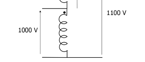
A single phase, 50 kVA, 1000V/100 V two winding transformer is connected as an autotransformer as shown in the figure. The kVA rating of the autotransformer is ______________.

Question diagram

Open complete paper

Showing 20 of 41 questions