My Cart
Your Cart 0

    Your cart is empty.

  • Total (Amount) ₹0.00
Previous year question hub

Power-system Stability - Power Systems - Electrical Engineering Previous Year Questions

Practice Power-system Stability - Power Systems - Electrical Engineering previous year questions organised from real papers, with year-wise coverage and clear topic navigation.

14Papers
10Years
15Questions
1Topics

Power-system Stability question pattern

Every graph below is calculated only from this selection.

Questions by year

Year-wise coverage for Power-system Stability. Each bar uses a separate theme-derived color.

Difficulty distribution

How the classified questions are distributed by difficulty.

Medium 6 40%
Easy 5 33.3%
Hard 4 26.7%
Question type distribution

MCQ, numerical, multiple-select and other formats found in these papers.

MCQ 10 66.7%
Numerical Answer Type (NAT) 5 33.3%

Subject weightage

Top subjects by unique question coverage.

Electrical Engineering
15 Qs

Most asked topics

Top topics across the included previous year papers.

Power Systems
15 Qs

Subtopic coverage

Top subtopics inside this exact selection.

Power-system Stability
15 Qs

Paper coverage

Question coverage for the most populated papers. Every active PYP paper remains listed below.

Electrical Engineering (EE) 2024
1 Qs
Electrical Engineering (EE) 2022
1 Qs
Electrical Engineering (EE) 2018
2 Qs
Electrical Engineering (EE) 2017 [Session 1]
1 Qs
Electrical Engineering (EE) 2017 [Session 2]
1 Qs
Electrical Engineering (EE) 2016 [Session 2]
1 Qs
Electrical Engineering (EE) 2013 [Session 1]
1 Qs
Electrical Engineering (EE) 2013 [Session 2]
1 Qs
Electrical Engineering (EE) 2013 [Session 3]
1 Qs
Electrical Engineering (EE) 2013 [Session 4]
1 Qs
Electrical Engineering (EE) 2012
1 Qs
Electrical Engineering (EE) 2009
1 Qs
Electrical Engineering (EE) 2008
1 Qs
Electrical Engineering (EE) 2007
1 Qs

Included previous year papers

Newest papers appear first. Sort by year, question coverage or name.

PaperYear / sessionQuestions in this viewOpen
Electrical Engineering (EE) 202420241View paper
Electrical Engineering (EE) 202220221View paper
Electrical Engineering (EE) 201820182View paper
Electrical Engineering (EE) 2017 [Session 1]20171View paper
Electrical Engineering (EE) 2017 [Session 2]20171View paper
Electrical Engineering (EE) 2016 [Session 2]20161View paper
Electrical Engineering (EE) 2013 [Session 1]20131View paper
Electrical Engineering (EE) 2013 [Session 2]20131View paper
Electrical Engineering (EE) 2013 [Session 3]20131View paper
Electrical Engineering (EE) 2013 [Session 4]20131View paper
Electrical Engineering (EE) 201220121View paper
Electrical Engineering (EE) 200920091View paper
Electrical Engineering (EE) 200820081View paper
Electrical Engineering (EE) 200720071View paper

All Power-system Stability previous year questions

Practice every matching question in batches of 20, with every available option.

1
2007 · Electrical Engineering · Power Systems · Power-system Stability
Electrical Engineering (EE) 2007
Consider a synchronous generator connected to an infinite bus by two identical parallel transmission lines. The transient reactance \(x'\) of the generator is 0.1 pu and the mechanical power input to it is constant at 1.0 pu. Due to some previous disturbance, the rotor angle (\(\delta\)) is undergoing an undamped oscillation, with the maximum value of \(\delta(t)\) equal to 130°. One of the parallel lines trips due to relay maloperation at an instant when \(\delta(t) = 130°\) as shown in the figure. The maximum value of the per unit line reactance, \(x\), such that the system does not lose synchronism subsequent to this tripping is
Open complete paper
2
2008 · Electrical Engineering · Power Systems · Power-system Stability
Electrical Engineering (EE) 2008
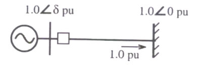
A lossless single machine infinite bus power system is shown below: [Image of system] The synchronous generator transfers 1.0 per unit of power to the infinite bus. The critical clearing time of circuit breaker is 0.28 s. If another identical synchronous generator is connected in parallel to the existing generator and each generator is scheduled to supply 0.5 per unit of power, then the critical clearing time of the circuit breaker will

Question diagram

Open complete paper
3
2009 · Electrical Engineering · Power Systems · Power-system Stability
Electrical Engineering (EE) 2009
A 500 MW, 21 kV, 50 Hz, 3-phase, 2-pole synchronous generator having a rated p.f.=0.9, has a moment of inertia of 27.5 × 10³ kg-m². The inertia constant (H) will be
Open complete paper
4
2012 · Electrical Engineering · Power Systems · Power-system Stability
Electrical Engineering (EE) 2012
A cylindrical rotor generator delivers 0.5 pu power in the steady-state to an infinite bus through a transmission line of reactance 0.5 pu. The generator no-load voltage is 1.5 pu and the infinite bus voltage is 1 pu. The inertia constant of the generator is 5 MW-s/MVA and the generator reactance is 1 pu. The critical clearing angle, in degrees, for a three-phase dead short circuit fault at the generator terminal is
(A) 53.5
(B) 60.2
(C) 70.8
(D) 79.6
Open complete paper
5
2013 · Electrical Engineering · Power Systems · Power-system Stability
Electrical Engineering (EE) 2013 [Session 1]
The angle \(\delta\) in the swing equation of a synchronous generator is the
Open complete paper
6
2013 · Electrical Engineering · Power Systems · Power-system Stability
Electrical Engineering (EE) 2013 [Session 2]
The angle \( \delta \) in the swing equation of a synchronous generator is the
Open complete paper
7
2016 · Electrical Engineering · Power Systems · Power-system Stability
Electrical Engineering (EE) 2016 [Session 2]
The single line diagram of a balanced power system is shown in the figure. The voltage magnitude at the generator internal bus is constant and 1.0 p.u. The p.u. reactances of different components in the system are also shown in the figure. The infinite bus voltage magnitude is 1.0 p.u. A three phase fault occurs at the middle of line 2. The ratio of the maximum real power that can be transferred during the pre-fault condition to the maximum real power that can be transferred under the faulted condition is ______.
Open complete paper
8
2017 · Electrical Engineering · Power Systems · Power-system Stability
Electrical Engineering (EE) 2017 [Session 1]
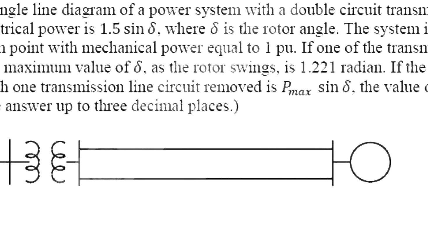
The figure shows the single line diagram of a power system with a double circuit transmission line. The expression for electrical power is \(1.5\sin\delta\), where \(\delta\) is the rotor angle. The system is operating at the stable equilibrium point with mechanical power equal to 1 pu. If one of the transmission line circuits is removed, the maximum value of \(\delta\), as the rotor swings, is 1.221 radian. If the expression for electrical power with one transmission line circuit removed is \(P_{max}\sin\delta\), the value of \(P_{max}\), in pu is _____. (Give the answer up to three decimal places.)
Open complete paper
9
2017 · Electrical Engineering · Power Systems · Power-system Stability
Electrical Engineering (EE) 2017 [Session 2]

A 3-phase, 2-pole, 50 Hz, synchronous generator has a rating of 250 MVA, 0.8 pf lagging. The kinetic energy of the machine at synchronous speed is 1000 MJ. The machine is running steadily at synchronous speed and delivering 60 MW power at a power angle of 10 electrical degrees. If the load is suddenly removed, assuming the acceleration is constant for 10 cycles, the value of the power angle after 5 cycles is ______ electrical degrees.

Open complete paper
10
2018 · Electrical Engineering · Power Systems · Power-system Stability
Electrical Engineering (EE) 2018
Consider a lossy transmission line with \(V_1\) and \(V_2\) as the sending and receiving end voltages, respectively. \(Z\) and \(X\) are the series impedance and reactance of the line, respectively. The steady-state stability limit for the transmission line will be
Open complete paper
11
2018 · Electrical Engineering · Power Systems · Power-system Stability
Electrical Engineering (EE) 2018
The per-unit power output of a salient-pole generator which is connected to an infinite bus, is given by the expression, \(P = 1.4 \sin \delta + 0.15 \sin 2\delta\), where \(\delta\) is the load angle. Newton-Raphson method is used to calculate the value of \(\delta\) for \(P = 0.8\) pu. If the initial guess is \(30^\circ\), then its value (in degree) at the end of the first iteration is
Open complete paper
12
2022 · Electrical Engineering · Power Systems · Power-system Stability
Electrical Engineering (EE) 2022
A 20 MVA, 11.2 kV, 4-pole, 50 Hz alternator has an inertia constant of 15 MJ/MVA. If the input and output powers of the alternator are 15 MW and 10 MW, respectively, the angular acceleration in mechanical degree/s² is __________. (round off to nearest integer)
Open complete paper
13
2024 · Electrical Engineering · Power Systems · Power-system Stability
Electrical Engineering (EE) 2024
The single line diagram of a lossless system is shown in the figure. The system is operating in steady-state at a stable equilibrium point with the power output of the generator being \(P_{max} \sin \delta\), where \(\delta\) is the load angle and the mechanical power input is \(0.5P_{max}\). A fault occurs on line 2 such that the power output of the generator is less than \(0.5P_{max}\) during the fault. After the fault is cleared by opening line 2, the power output of the generator is \((P_{max}/\sqrt{2}) \sin \delta\). If the critical fault clearing angle is \(\pi/2\) radians, the accelerating area on the power angle curve is ______ times \(P_{max}\) (rounded off to 2 decimal places).
Open complete paper