My Cart
Your Cart 0

    Your cart is empty.

  • Total (Amount) ₹0.00
Previous year question hub

Load Flow, Economic Dispatch and Compensation - Power Systems - Electrical Engineering Previous Year Questions

Practice Load Flow, Economic Dispatch and Compensation - Power Systems - Electrical Engineering previous year questions organised from real papers, with year-wise coverage and clear topic navigation.

24Papers
18Years
50Questions
1Topics

Load Flow, Economic Dispatch and Compensation question pattern

Every graph below is calculated only from this selection.

Questions by year

Year-wise coverage for Load Flow, Economic Dispatch and Compensation. Each bar uses a separate theme-derived color.

Difficulty distribution

How the classified questions are distributed by difficulty.

Medium 37 74%
Easy 11 22%
Hard 2 4%
Question type distribution

MCQ, numerical, multiple-select and other formats found in these papers.

MCQ 38 76%
Numerical Answer Type (NAT) 11 22%
MSQ 1 2%

Subject weightage

Top subjects by unique question coverage.

Electrical Engineering
50 Qs

Most asked topics

Top topics across the included previous year papers.

Power Systems
50 Qs

Subtopic coverage

Top subtopics inside this exact selection.

Load Flow, Economic Dispatch and Compensation
50 Qs

Paper coverage

Question coverage for the most populated papers. Every active PYP paper remains listed below.

Electrical Engineering (EE) 2025
1 Qs
Electrical Engineering (EE) 2024
3 Qs
Electrical Engineering (EE) 2023
3 Qs
Electrical Engineering (EE) 2022
2 Qs
Electrical Engineering (EE) 2021
3 Qs
Electrical Engineering (EE) 2020
2 Qs
Electrical Engineering (EE) 2019
1 Qs
Electrical Engineering (EE) 2018
2 Qs
Electrical Engineering (EE) 2017 [Session 1]
4 Qs
Electrical Engineering (EE) 2017 [Session 2]
3 Qs
Electrical Engineering (EE) 2016 [Session 1]
2 Qs
Electrical Engineering (EE) 2016 [Session 2]
1 Qs
Electrical Engineering (EE) 2014 [Session 1]
2 Qs
Electrical Engineering (EE) 2014 [Session 2]
2 Qs
Electrical Engineering (EE) 2013 [Session 1]
2 Qs
Electrical Engineering (EE) 2013 [Session 2]
2 Qs
Electrical Engineering (EE) 2013 [Session 3]
2 Qs
Electrical Engineering (EE) 2013 [Session 4]
2 Qs
Electrical Engineering (EE) 2012
3 Qs
Electrical Engineering (EE) 2011
3 Qs
Electrical Engineering (EE) 2010
1 Qs
Electrical Engineering (EE) 2009
2 Qs
Electrical Engineering (EE) 2008
1 Qs
Electrical Engineering (EE) 2007
1 Qs

Included previous year papers

Newest papers appear first. Sort by year, question coverage or name.

PaperYear / sessionQuestions in this viewOpen
Electrical Engineering (EE) 202520251View paper
Electrical Engineering (EE) 202420243View paper
Electrical Engineering (EE) 202320233View paper
Electrical Engineering (EE) 202220222View paper
Electrical Engineering (EE) 202120213View paper
Electrical Engineering (EE) 202020202View paper
Electrical Engineering (EE) 201920191View paper
Electrical Engineering (EE) 201820182View paper
Electrical Engineering (EE) 2017 [Session 1]20174View paper
Electrical Engineering (EE) 2017 [Session 2]20173View paper
Electrical Engineering (EE) 2016 [Session 1]20162View paper
Electrical Engineering (EE) 2016 [Session 2]20161View paper
Electrical Engineering (EE) 2014 [Session 1]20142View paper
Electrical Engineering (EE) 2014 [Session 2]20142View paper
Electrical Engineering (EE) 2013 [Session 1]20132View paper
Electrical Engineering (EE) 2013 [Session 2]20132View paper
Electrical Engineering (EE) 2013 [Session 3]20132View paper
Electrical Engineering (EE) 2013 [Session 4]20132View paper
Electrical Engineering (EE) 201220123View paper
Electrical Engineering (EE) 201120113View paper
Electrical Engineering (EE) 201020101View paper
Electrical Engineering (EE) 200920092View paper
Electrical Engineering (EE) 200820081View paper
Electrical Engineering (EE) 200720071View paper

All Load Flow, Economic Dispatch and Compensation previous year questions

Practice every matching question in batches of 20, with every available option.

1
2007 · Electrical Engineering · Power Systems · Load Flow, Economic Dispatch and Compensation
Electrical Engineering (EE) 2007
Consider the two power systems shown in figure A below, which are initially not interconnected, and are operating in steady state at the same frequency. Separate load flow solutions are computed individually for the two systems, corresponding to this scenario. The bus voltage phasors so obtained are indicated on figure A. These two isolated systems are now interconnected by a short transmission line as shown in figure B, and it is found that P₁ = P₂ = Q₁ = Q₂ = 0.

The bus voltage phase angular difference between generator bus X and generator bus Y after the interconnection is
Open complete paper
2
2008 · Electrical Engineering · Power Systems · Load Flow, Economic Dispatch and Compensation
Electrical Engineering (EE) 2008
A lossless power system has to serve a load of 250 MW. There are two generators (G1 and G2) in the system with cost curves \(C_1\) and \(C_2\) respectively defined as follows: \(C_1(P_{G1}) = P_{G1} + 0.055 \times P_{G1}^2\) \(C_2(P_{G2}) = 3P_{G2} + 0.03 \times P_{G2}^2\) where \(P_{G1}\) and \(P_{G2}\) are the MW injections from generator G1 and G2 respectively. Then, the minimum cost dispatch will be
Open complete paper
3
2009 · Electrical Engineering · Power Systems · Load Flow, Economic Dispatch and Compensation
Electrical Engineering (EE) 2009
For the Y-bus matrix of a 4-bus system given in per unit, the buses having shunt elements are
\(Y_{BUS} = j\begin{bmatrix}-5 & 2 & 2.5 & 0 \\ 2 & -10 & 2.5 & 4 \\ 2.5 & 2.5 & -9 & 4 \\ 0 & 4 & 4 & -8\end{bmatrix}\)
Open complete paper
4
2009 · Electrical Engineering · Power Systems · Load Flow, Economic Dispatch and Compensation
Electrical Engineering (EE) 2009
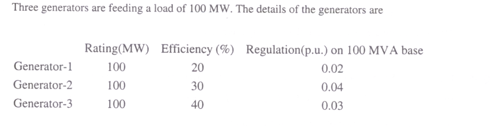
Three generators are feeding a load of 100 MW. The details of the generators are

Rating(MW)Efficiency (%)Regulation(p.u.) on 100 MVA base
Generator-1100200.02
Generator-2100300.04
Generator-3100400.03

In the event of increased load power demand, which of the following will happen?

Question diagram

Open complete paper
5
2010 · Electrical Engineering · Power Systems · Load Flow, Economic Dispatch and Compensation
Electrical Engineering (EE) 2010
Consider two buses connected by an impedance of (0+j5) Ω. The bus 1 voltage is 100∠30° V, and bus 2 voltage is 100∠0° V. The real and reactive power supplied by bus 1, respectively, are
Open complete paper
6
2011 · Electrical Engineering · Power Systems · Load Flow, Economic Dispatch and Compensation
Electrical Engineering (EE) 2011

For enhancing the power transmission in a long EHV transmission line, the most preferred method is to connect a

Open complete paper
7
2011 · Electrical Engineering · Power Systems · Load Flow, Economic Dispatch and Compensation
Electrical Engineering (EE) 2011

A load center of 120 MW derives power from two power stations connected by 220 kV transmission lines of 25 km and 75 km as shown in the figure below. The three generators G1, G2 and G3 are of 100 MW capacity each and have identical fuel cost characteristics. The minimum loss generation schedule for supplying the 120 MW load is

Question diagram

Open complete paper
8
2011 · Electrical Engineering · Power Systems · Load Flow, Economic Dispatch and Compensation
Electrical Engineering (EE) 2011

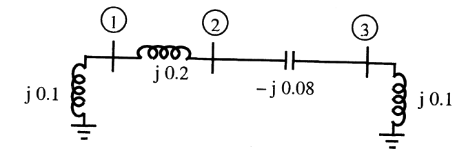
A three-bus network is shown in the figure below indicating the p.u. impedances of each element.

Question diagram

The Bus admittance matrix, Y-bus, of the network is
Open complete paper
9
2012 · Electrical Engineering · Power Systems · Load Flow, Economic Dispatch and Compensation
Electrical Engineering (EE) 2012
The bus admittance matrix of a three-bus three-line system is \[Y = j\begin{bmatrix}-13 & 10 & 5 \\ 10 & -18 & 10 \\ 5 & 10 & -13\end{bmatrix}\] If each transmission line between the two buses is represented by an equivalent \(\pi\)-network, the magnitude of the shunt susceptance of the line connecting bus 1 and 2 is
Open complete paper
10
2012 · Electrical Engineering · Power Systems · Load Flow, Economic Dispatch and Compensation
Electrical Engineering (EE) 2012
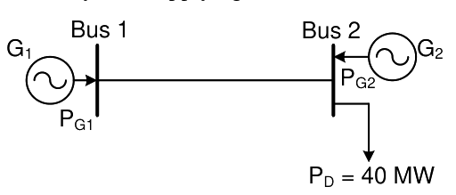
The figure shows a two-generator system supplying a load of P_D = 40 MW, connected at bus 2.
The fuel cost of generators G_1 and G_2 are : C_1(P_G1) = 10,000 Rs/MWh and C_2(P_G2) = 12,500 Rs/MWh and the loss in the line is P_loss(pu) = 0.5 P_G1^2(pu), where the loss coefficient is specified in pu on a 100 MVA base. The most economic power generation schedule in MW is
(A) P_G1 = 20, P_G2 = 22
(B) P_G1 = 22, P_G2 = 20
(C) P_G1 = 20, P_G2 = 20
(D) P_G1 = 0, P_G2 = 40

Question diagram

Open complete paper
11
2012 · Electrical Engineering · Power Systems · Load Flow, Economic Dispatch and Compensation
Electrical Engineering (EE) 2012
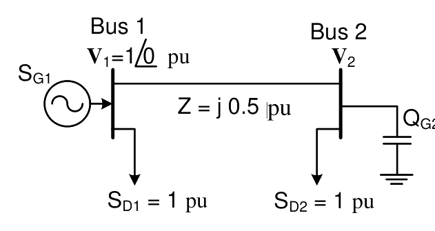
For the system shown below, S_D1 and S_D2 are complex power demands at bus 1 and bus 2 respectively. If |V_2| = 1 pu, the VAR rating of the capacitor (Q_G2) connected at bus 2 is
(A) 0.2 pu
(B) 0.268 pu
(C) 0.312 pu
(D) 0.4 pu

Question diagram

Open complete paper
12
2013 · Electrical Engineering · Power Systems · Load Flow, Economic Dispatch and Compensation
Electrical Engineering (EE) 2013 [Session 1]
The voltage phase angles in rad at buses 2 and 3 are
Open complete paper
13
2013 · Electrical Engineering · Power Systems · Load Flow, Economic Dispatch and Compensation
Electrical Engineering (EE) 2013 [Session 1]
If the base impedance and the line-to-line base voltage are \(100 \Omega\) and \(100 \text{ kV}\), respectively, then the real power in MW delivered by the generator connected at the slack bus is
Open complete paper
14
2013 · Electrical Engineering · Power Systems · Load Flow, Economic Dispatch and Compensation
Electrical Engineering (EE) 2013 [Session 2]
If the base impedance and the line-to-line base voltage are 100 Ω and 100 kV, respectively, then the real power in MW delivered by the generator connected at the slack bus is
Open complete paper
15
2013 · Electrical Engineering · Power Systems · Load Flow, Economic Dispatch and Compensation
Electrical Engineering (EE) 2013 [Session 3]
If the base impedance and the line-to-line base voltage are \(100\ \Omega\) and \(100\ \text{kV}\), respectively, then the real power in MW delivered by the generator connected at the slack bus is
Open complete paper
16
2014 · Electrical Engineering · Power Systems · Load Flow, Economic Dispatch and Compensation
Electrical Engineering (EE) 2014 [Session 1]
A two bus power system shown in the figure supplies load of 1.0+j0.5 p.u.

The values of V1 in p.u. and δ2 respectively are
Open complete paper
17
2014 · Electrical Engineering · Power Systems · Load Flow, Economic Dispatch and Compensation
Electrical Engineering (EE) 2014 [Session 1]
The fuel cost functions of two power plants are
Plant P1: C1 = 0.05Pg12 + APg1 + B
Plant P2: C2 = 0.10Pg22 + 3APg2 + 2B

where, Pg1 and Pg2 are the generated powers of two plants, and A and B are the constants. If the two plants optimally share 1000 MW load at incremental fuel cost of 100 Rs/MWh, the ratio of load shared by plants P1 and P2 is
Open complete paper
18
2014 · Electrical Engineering · Power Systems · Load Flow, Economic Dispatch and Compensation
Electrical Engineering (EE) 2014 [Session 2]
A single phase induction motor draws 12 MW power at 0.6 lagging power. A capacitor is connected in parallel to the motor to improve the power factor of the combination of motor and capacitor to 0.8 lagging. Assuming that the real and reactive power drawn by the motor remains same as before, the reactive power delivered by the capacitor in MVAR is ______________.
Open complete paper
19
2014 · Electrical Engineering · Power Systems · Load Flow, Economic Dispatch and Compensation
Electrical Engineering (EE) 2014 [Session 2]
There are two generators in a power system. No-load frequencies of the generators are 51.5 Hz and 51 Hz, respectively, and both have droop constant of 1 Hz/MW. Total load in the system is 2.5 MW. Assuming that the generators are operating under their respective droop characteristics, the frequency of the power system in Hz in the steady state is __________.
Open complete paper
20
2016 · Electrical Engineering · Power Systems · Load Flow, Economic Dispatch and Compensation
Electrical Engineering (EE) 2016 [Session 1]
In a 100 bus power system, there are 10 generators. In a particular iteration of Newton Raphson load flow technique (in polar coordinates), two of the PV buses are converted to PQ type. In this iteration,
Open complete paper

Showing 20 of 46 questions