My Cart
Your Cart 0

    Your cart is empty.

  • Total (Amount) ₹0.00
Previous year question hub

Inverters and Pulse-width Modulation - Power Electronics - Electrical Engineering Previous Year Questions

Practice Inverters and Pulse-width Modulation - Power Electronics - Electrical Engineering previous year questions organised from real papers, with year-wise coverage and clear topic navigation.

20Papers
14Years
29Questions
1Topics

Inverters and Pulse-width Modulation question pattern

Every graph below is calculated only from this selection.

Questions by year

Year-wise coverage for Inverters and Pulse-width Modulation. Each bar uses a separate theme-derived color.

Difficulty distribution

How the classified questions are distributed by difficulty.

Medium 27 93.1%
Hard 2 6.9%

Question type distribution

MCQ, numerical, multiple-select and other formats found in these papers.

MCQ 17 58.6%
Numerical Answer Type (NAT) 12 41.4%

Subject weightage

Top subjects by unique question coverage.

Electrical Engineering
29 Qs

Most asked topics

Top topics across the included previous year papers.

Power Electronics
29 Qs

Subtopic coverage

Top subtopics inside this exact selection.

Inverters and Pulse-width Modulation
29 Qs

Paper coverage

Question coverage for the most populated papers. Every active PYP paper remains listed below.

Electrical Engineering (EE) 2024
1 Qs
Electrical Engineering (EE) 2022
2 Qs
Electrical Engineering (EE) 2021
1 Qs
Electrical Engineering (EE) 2020
1 Qs
Electrical Engineering (EE) 2019
1 Qs
Electrical Engineering (EE) 2017 [Session 1]
2 Qs
Electrical Engineering (EE) 2017 [Session 2]
2 Qs
Electrical Engineering (EE) 2016 [Session 1]
2 Qs
Electrical Engineering (EE) 2016 [Session 2]
2 Qs
Electrical Engineering (EE) 2014 [Session 1]
1 Qs
Electrical Engineering (EE) 2014 [Session 3]
1 Qs
Electrical Engineering (EE) 2013 [Session 1]
1 Qs
Electrical Engineering (EE) 2013 [Session 2]
1 Qs
Electrical Engineering (EE) 2013 [Session 3]
1 Qs
Electrical Engineering (EE) 2013 [Session 4]
1 Qs
Electrical Engineering (EE) 2012
2 Qs
Electrical Engineering (EE) 2011
1 Qs
Electrical Engineering (EE) 2009
1 Qs
Electrical Engineering (EE) 2008
2 Qs
Electrical Engineering (EE) 2007
3 Qs

Included previous year papers

Newest papers appear first. Sort by year, question coverage or name.

PaperYear / sessionQuestions in this viewOpen
Electrical Engineering (EE) 202420241View paper
Electrical Engineering (EE) 202220222View paper
Electrical Engineering (EE) 202120211View paper
Electrical Engineering (EE) 202020201View paper
Electrical Engineering (EE) 201920191View paper
Electrical Engineering (EE) 2017 [Session 1]20172View paper
Electrical Engineering (EE) 2017 [Session 2]20172View paper
Electrical Engineering (EE) 2016 [Session 1]20162View paper
Electrical Engineering (EE) 2016 [Session 2]20162View paper
Electrical Engineering (EE) 2014 [Session 1]20141View paper
Electrical Engineering (EE) 2014 [Session 3]20141View paper
Electrical Engineering (EE) 2013 [Session 1]20131View paper
Electrical Engineering (EE) 2013 [Session 2]20131View paper
Electrical Engineering (EE) 2013 [Session 3]20131View paper
Electrical Engineering (EE) 2013 [Session 4]20131View paper
Electrical Engineering (EE) 201220122View paper
Electrical Engineering (EE) 201120111View paper
Electrical Engineering (EE) 200920091View paper
Electrical Engineering (EE) 200820082View paper
Electrical Engineering (EE) 200720073View paper

All Inverters and Pulse-width Modulation previous year questions

Practice every matching question in batches of 20, with every available option.

1
2007 · Electrical Engineering · Power Electronics · Inverters and Pulse-width Modulation
Electrical Engineering (EE) 2007
“Six MOSFETs connected in a bridge configuration (having no other power device) MUST be operated as a Voltage Source Inverter (VSI)”. This statement is
Open complete paper
2
2007 · Electrical Engineering · Power Electronics · Inverters and Pulse-width Modulation
Electrical Engineering (EE) 2007
The figure below shows a three phase self-commutated voltage source converter connected to a power system. The converter's dc bus capacitor is marked as C in the figure. The circuit is initially operating in steady state with \(\delta = 0\) and the capacitor dc voltage is equal to \(V_{dc0}\). You may neglect all losses and harmonics. What action should be taken to increase the capacitor dc voltage slowly to a new steady state value?
Open complete paper
3
2007 · Electrical Engineering · Power Electronics · Inverters and Pulse-width Modulation
Electrical Engineering (EE) 2007
A single-phase voltage source inverter is controlled in a single pulse-width modulated mode with a pulse width of 150° in each half cycle. Total harmonic distortion is defined as THD = √(V_rms² - V₁²)/V₁ ×100, where V₁ is the rms value of the fundamental component of the output voltage. The THD of output ac voltage waveform is
Open complete paper
4
2008 · Electrical Engineering · Power Electronics · Inverters and Pulse-width Modulation
Electrical Engineering (EE) 2008

A 3-phase Voltage Source Inverter is operated in 180° conduction mode. Which one of the following statements is true?

Open complete paper
5
2008 · Electrical Engineering · Power Electronics · Inverters and Pulse-width Modulation
Electrical Engineering (EE) 2008
A single phase voltage source inverter is feeding a purely inductive load as shown in the figure.

The inverter is operated at 50 Hz in 180° square wave mode. Assume that the load current does not have any dc component. The peak value of the inductor current iL will be
Open complete paper
6
2009 · Electrical Engineering · Power Electronics · Inverters and Pulse-width Modulation
Electrical Engineering (EE) 2009
The Current Source Inverter shown in figure is operated by alternately turning on thyristor pairs (T1, T2) and (T3, T4). If the load is purely resistive, the theoretical maximum output frequency obtainable will be
Open complete paper
7
2011 · Electrical Engineering · Power Electronics · Inverters and Pulse-width Modulation
Electrical Engineering (EE) 2011
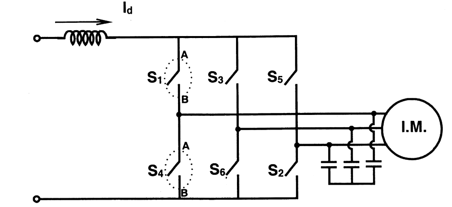
A three-phase current source inverter used for the speed control of an induction motor is to be realized using MOSFET switches as shown below. Switches S1 to S6 are identical switches.

The proper configuration for realizing switches S1 to S6 is

Question diagram

Open complete paper
8
2012 · Electrical Engineering · Power Electronics · Inverters and Pulse-width Modulation
Electrical Engineering (EE) 2012
The rms value of load phase voltage is

Question diagram

Open complete paper
9
2012 · Electrical Engineering · Power Electronics · Inverters and Pulse-width Modulation
Electrical Engineering (EE) 2012
If the dc bus voltage Vd = 300 V, the power consumed by 3-phase load is
Open complete paper
10
2013 · Electrical Engineering · Power Electronics · Inverters and Pulse-width Modulation
Electrical Engineering (EE) 2013 [Session 1]
In the interval when \(v_o < 0\) and \(i_o > 0\) the pair of devices which conducts the load current is
Open complete paper
11
2013 · Electrical Engineering · Power Electronics · Inverters and Pulse-width Modulation
Electrical Engineering (EE) 2013 [Session 2]
In the interval when vo < 0 and io > 0 the pair of devices which conducts the load current is
Open complete paper
12
2013 · Electrical Engineering · Power Electronics · Inverters and Pulse-width Modulation
Electrical Engineering (EE) 2013 [Session 4]
In the interval when v0 < 0 and i0 > 0 the pair of devices which conducts the load current is
Open complete paper
13
2014 · Electrical Engineering · Power Electronics · Inverters and Pulse-width Modulation
Electrical Engineering (EE) 2014 [Session 1]
The figure shows one period of the output voltage of an inverter. α should be chosen such that 60° < α < 90°. If rms value of the fundamental component is 50 V, then α in degree is ______
Open complete paper
14
2014 · Electrical Engineering · Power Electronics · Inverters and Pulse-width Modulation
Electrical Engineering (EE) 2014 [Session 3]
A single-phase voltage source inverter shown in figure is feeding power to a load. The triggering pulses of the devices are also shown in the figure.

If the load current is sinusoidal and is zero at 0, π, 2π,..., the node voltage VAO has the waveform
Open complete paper
15
2016 · Electrical Engineering · Power Electronics · Inverters and Pulse-width Modulation
Electrical Engineering (EE) 2016 [Session 1]
The switches T1 and T2 in Figure (a) are switched in a complementary fashion with sinusoidal pulse width modulation technique. The modulating voltage \(v_m(t) = 0.8 \sin (200\pi t)\) V and the triangular carrier voltage \(v_c\) are as shown in Figure (b). The carrier frequency is 5 kHz. The peak value of the 100 Hz component of the load current \(i_L\), in Ampere, is ________.
Open complete paper
16
2016 · Electrical Engineering · Power Electronics · Inverters and Pulse-width Modulation
Electrical Engineering (EE) 2016 [Session 1]
A single-phase full-bridge voltage source inverter (VSI) is fed from a 300 V battery. A pulse of 120° duration is used to trigger the appropriate devices in each half-cycle. The rms value of the fundamental component of the output voltage, in volts, is
Open complete paper
17
2016 · Electrical Engineering · Power Electronics · Inverters and Pulse-width Modulation
Electrical Engineering (EE) 2016 [Session 2]
A three-phase Voltage Source Inverter (VSI) as shown in the figure is feeding a delta connected resistive load of 30 Ω/phase. If it is fed from a 600 V battery, with 180° conduction of solid-state devices, the power consumed by the load, in kW, is ______.
Open complete paper
18
2016 · Electrical Engineering · Power Electronics · Inverters and Pulse-width Modulation
Electrical Engineering (EE) 2016 [Session 2]
A single-phase bi-directional voltage source converter (VSC) is shown in the figure below. All devices are ideal. It is used to charge a battery at 400 V with power of 5 kW from a source \(V_s\) = 220 V (rms), 50 Hz sinusoidal AC mains at unity p.f. If its AC side interfacing inductor is 5 mH and the switches are operated at 20 kHz, then the phase shift (δ) between AC mains voltage (\(V_s\)) and fundamental AC rms VSC voltage (\(V_{C1}\)), in degree, is ______.
Open complete paper
19
2017 · Electrical Engineering · Power Electronics · Inverters and Pulse-width Modulation
Electrical Engineering (EE) 2017 [Session 1]
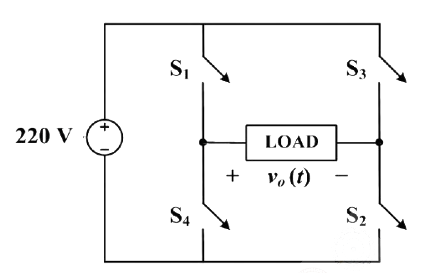
In the converter circuit shown below, the switches are controlled such that the load voltage $v_o(t)$ is a 400 Hz square wave.

The RMS value of the fundamental component of $v_o(t)$ in volts is ________.

Question diagram

Open complete paper
20
2017 · Electrical Engineering · Power Electronics · Inverters and Pulse-width Modulation
Electrical Engineering (EE) 2017 [Session 1]
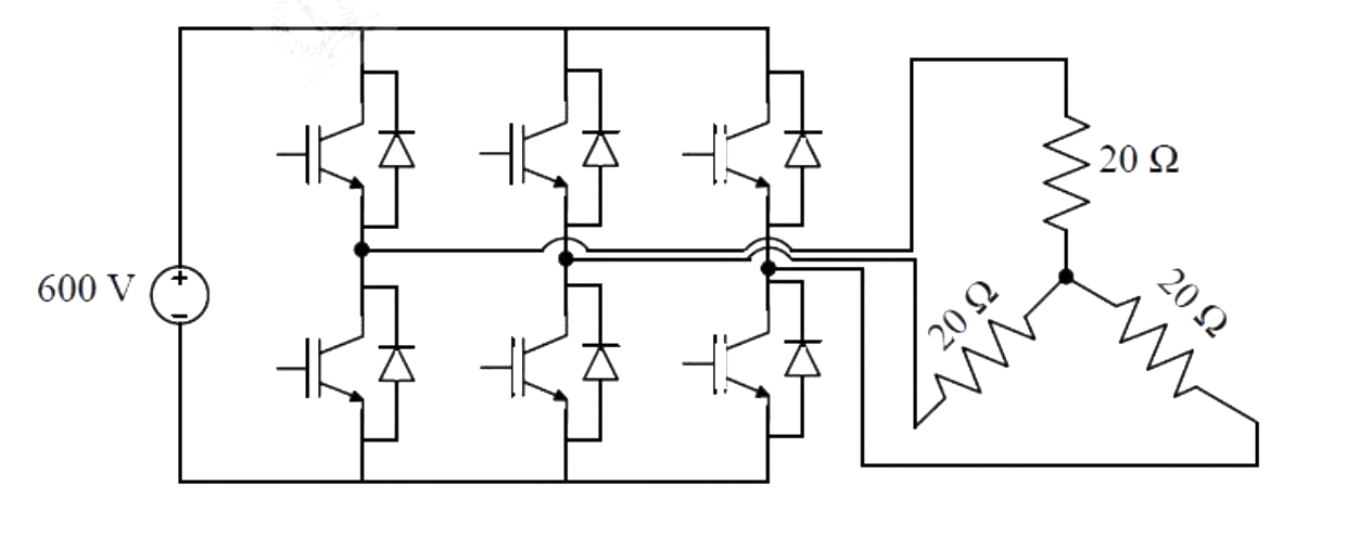
A 3-phase voltage source inverter is supplied from a 600V DC source as shown in the figure below. For a star connected resistive load of $20\Omega$ per phase, the load power for $120^{\circ}$ device conduction, in kW, is ________.

Question diagram

Open complete paper

Showing 20 of 28 questions