My Cart
Your Cart 0

    Your cart is empty.

  • Total (Amount) ₹0.00
Previous year question hub

Time and Frequency Response - Control Systems - Electrical Engineering Previous Year Questions

Practice Time and Frequency Response - Control Systems - Electrical Engineering previous year questions organised from real papers, with year-wise coverage and clear topic navigation.

24Papers
17Years
47Questions
1Topics

Time and Frequency Response question pattern

Every graph below is calculated only from this selection.

Questions by year

Year-wise coverage for Time and Frequency Response. Each bar uses a separate theme-derived color.

Difficulty distribution

How the classified questions are distributed by difficulty.

Medium 31 66%
Easy 15 31.9%
Hard 1 2.1%

Question type distribution

MCQ, numerical, multiple-select and other formats found in these papers.

MCQ 36 76.6%
Numerical Answer Type (NAT) 9 19.1%
MSQ 2 4.3%

Subject weightage

Top subjects by unique question coverage.

Electrical Engineering
47 Qs

Most asked topics

Top topics across the included previous year papers.

Control Systems
47 Qs

Subtopic coverage

Top subtopics inside this exact selection.

Time and Frequency Response
47 Qs

Paper coverage

Question coverage for the most populated papers. Every active PYP paper remains listed below.

Electrical Engineering (EE) 2025
1 Qs
Electrical Engineering (EE) 2024
4 Qs
Electrical Engineering (EE) 2023
1 Qs
Electrical Engineering (EE) 2022
3 Qs
Electrical Engineering (EE) 2021
1 Qs
Electrical Engineering (EE) 2019
4 Qs
Electrical Engineering (EE) 2018
1 Qs
Electrical Engineering (EE) 2017 [Session 1]
3 Qs
Electrical Engineering (EE) 2017 [Session 2]
2 Qs
Electrical Engineering (EE) 2016 [Session 1]
3 Qs
Electrical Engineering (EE) 2016 [Session 2]
1 Qs
Electrical Engineering (EE) 2014 [Session 2]
2 Qs
Electrical Engineering (EE) 2014 [Session 1]
1 Qs
Electrical Engineering (EE) 2014 [Session 3]
1 Qs
Electrical Engineering (EE) 2013 [Session 1]
2 Qs
Electrical Engineering (EE) 2013 [Session 2]
1 Qs
Electrical Engineering (EE) 2013 [Session 3]
1 Qs
Electrical Engineering (EE) 2013 [Session 4]
1 Qs
Electrical Engineering (EE) 2012
2 Qs
Electrical Engineering (EE) 2011
2 Qs
Electrical Engineering (EE) 2010
2 Qs
Electrical Engineering (EE) 2009
3 Qs
Electrical Engineering (EE) 2008
3 Qs
Electrical Engineering (EE) 2007
2 Qs

Included previous year papers

Newest papers appear first. Sort by year, question coverage or name.

PaperYear / sessionQuestions in this viewOpen
Electrical Engineering (EE) 202520251View paper
Electrical Engineering (EE) 202420244View paper
Electrical Engineering (EE) 202320231View paper
Electrical Engineering (EE) 202220223View paper
Electrical Engineering (EE) 202120211View paper
Electrical Engineering (EE) 201920194View paper
Electrical Engineering (EE) 201820181View paper
Electrical Engineering (EE) 2017 [Session 1]20173View paper
Electrical Engineering (EE) 2017 [Session 2]20172View paper
Electrical Engineering (EE) 2016 [Session 1]20163View paper
Electrical Engineering (EE) 2016 [Session 2]20161View paper
Electrical Engineering (EE) 2014 [Session 1]20141View paper
Electrical Engineering (EE) 2014 [Session 2]20142View paper
Electrical Engineering (EE) 2014 [Session 3]20141View paper
Electrical Engineering (EE) 2013 [Session 1]20132View paper
Electrical Engineering (EE) 2013 [Session 2]20131View paper
Electrical Engineering (EE) 2013 [Session 3]20131View paper
Electrical Engineering (EE) 2013 [Session 4]20131View paper
Electrical Engineering (EE) 201220122View paper
Electrical Engineering (EE) 201120112View paper
Electrical Engineering (EE) 201020102View paper
Electrical Engineering (EE) 200920093View paper
Electrical Engineering (EE) 200820083View paper
Electrical Engineering (EE) 200720072View paper

All Time and Frequency Response previous year questions

Practice every matching question in batches of 20, with every available option.

1
2007 · Electrical Engineering · Control Systems · Time and Frequency Response
Electrical Engineering (EE) 2007
If x = Re G(jω) and y = Im G(jω) then for ω → 0⁺, the Nyquist plot for G(s) = 1/[s(s+1)(s+2)] becomes asymptotic to the line
Open complete paper
2
2007 · Electrical Engineering · Control Systems · Time and Frequency Response
Electrical Engineering (EE) 2007
For a step-input \(e_i\), the overshoot in the output \(e_0\) will be

Question diagram

Open complete paper
3
2008 · Electrical Engineering · Control Systems · Time and Frequency Response
Electrical Engineering (EE) 2008
The transfer function of a linear time invariant system is given as
G(s) = 1/(s2 + 3s + 2)
The steady state value of the output of this system for a unit impulse input applied at time instant t = 1 will be
Open complete paper
4
2008 · Electrical Engineering · Control Systems · Time and Frequency Response
Electrical Engineering (EE) 2008
The asymptotic Bode magnitude plot of a minimum phase transfer function is shown in the figure:

This transfer function has
Open complete paper
5
2008 · Electrical Engineering · Control Systems · Time and Frequency Response
Electrical Engineering (EE) 2008
The transfer function of a system is given as
100/(s2 + 20s + 100)
This system is
Open complete paper
6
2009 · Electrical Engineering · Control Systems · Time and Frequency Response
Electrical Engineering (EE) 2009

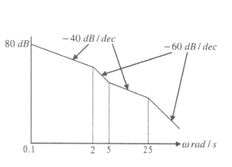
The asymptotic approximation of the log-magnitude vs frequency plot of a system containing only real poles and zeros is shown. Its transfer function is

Question diagram

Open complete paper
7
2009 · Electrical Engineering · Control Systems · Time and Frequency Response
Electrical Engineering (EE) 2009
The unit-step response of a unity feedback system with open loop transfer function \(G(s) = K/((s+1)(s+2))\) is shown in the figure. The value of K is
Open complete paper
8
2009 · Electrical Engineering · Control Systems · Time and Frequency Response
Electrical Engineering (EE) 2009
The open loop transfer function of a unity feedback system is given by \(G(s) = (e^{-0.1s})/s\). The gain margin of this system is
Open complete paper
9
2010 · Electrical Engineering · Control Systems · Time and Frequency Response
Electrical Engineering (EE) 2010
For the system \( \frac{2}{(s+1)} \), the approximate time taken for a step response to reach 98% of its final value is
Open complete paper
10
2010 · Electrical Engineering · Control Systems · Time and Frequency Response
Electrical Engineering (EE) 2010
The frequency response of \(G(s) = 1/[s(s+1)(s+2)]\) plotted in the complex \(G(jω)\) plane (for \(0 < ω < ∞\)) is
Open complete paper
11
2011 · Electrical Engineering · Control Systems · Time and Frequency Response
Electrical Engineering (EE) 2011
The frequency response of a linear system \(G(j\omega)\) is provided in the tabular form below
\(|G(j\omega)|\)1.31.21.00.80.50.3
\(\angle G(j\omega)\)\(-130^o\)\(-140^o\)\(-150^o\)\(-160^o\)\(-180^o\)\(-200^o\)

The gain margin and phase margin of the system are

Question diagram

Open complete paper
12
2011 · Electrical Engineering · Control Systems · Time and Frequency Response
Electrical Engineering (EE) 2011
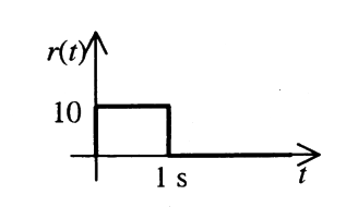
The steady state error of a unity feedback linear system for a unit step input is 0.1. The steady state error of the same system, for a pulse input \(r(t)\) having a magnitude of 10 and a duration of one second, as shown in the figure is

Question diagram

Open complete paper
13
2012 · Electrical Engineering · Control Systems · Time and Frequency Response
Electrical Engineering (EE) 2012
A system with transfer function \(G(s) = \frac{(s^2+9)(s+2)}{(s+1)(s+3)(s+4)}\) is excited by \(\sin(\omega t)\). The steady-state output of the system is zero at
Open complete paper
14
2012 · Electrical Engineering · Control Systems · Time and Frequency Response
Electrical Engineering (EE) 2012

The phase of the above lead compensator is maximum at

Open complete paper
15
2013 · Electrical Engineering · Control Systems · Time and Frequency Response
Electrical Engineering (EE) 2013 [Session 1]
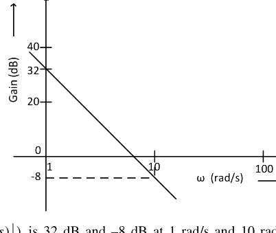
The Bode plot of a transfer function \( G(s) \) is shown in the figure below.
The gain ( \( 20 \log|G(s)| \) ) is 32 dB and \(-8\) dB at 1 rad/s and 10 rad/s respectively. The phase is negative for all \( \omega \). Then \( G(s) \) is
Open complete paper
16
2013 · Electrical Engineering · Control Systems · Time and Frequency Response
Electrical Engineering (EE) 2013 [Session 1]
The response \( y(t) \) to a unit step input is
Open complete paper
17
2013 · Electrical Engineering · Control Systems · Time and Frequency Response
Electrical Engineering (EE) 2013 [Session 2]
The Bode plot of a transfer function \( G(s) \) is shown in the figure below.
The gain \( 20 \log|G(s)| \) is 32 dB and –8 dB at 1 rad/s and 10 rad/s respectively. The phase is negative for all \( \omega \). Then \( G(s) \) is
Open complete paper
18
2013 · Electrical Engineering · Control Systems · Time and Frequency Response
Electrical Engineering (EE) 2013 [Session 3]
The Bode plot of a transfer function \( G(s) \) is shown in the figure below.
The gain \( (20 \log |G(s)|) \) is 32 dB and -8 dB at 1 rad/s and 10 rad/s respectively. The phase is negative for all \( \omega \). Then \( G(s) \) is

Question diagram

Open complete paper
19
2013 · Electrical Engineering · Control Systems · Time and Frequency Response
Electrical Engineering (EE) 2013 [Session 4]
The Bode plot of a transfer function \(G(s)\) is shown in the figure below. The gain \((20 \log |G(s)|)\) is 32 dB and \(-8\) dB at 1 rad/s and 10 rad/s respectively. The phase is negative for all \(\omega\). Then \(G(s)\) is
Open complete paper
20
2014 · Electrical Engineering · Control Systems · Time and Frequency Response
Electrical Engineering (EE) 2014 [Session 1]
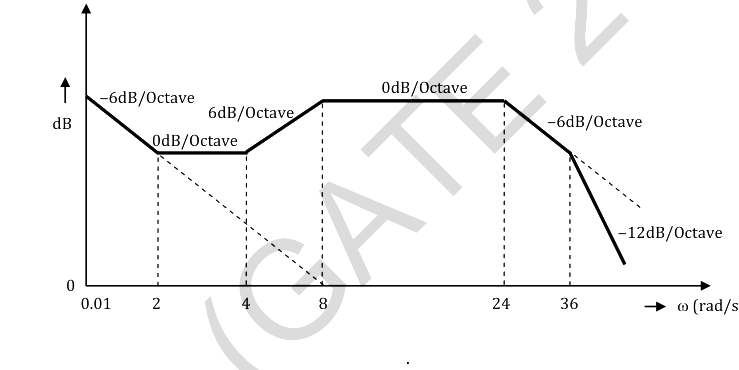
The Bode magnitude plot of the transfer function \(G(s) = \frac{K(1+0.5s)(1+as)}{s(1+\frac{s}{8})(1+\frac{bs}{s})(1+\frac{s}{36})}\) is shown below: Note that –6 dB/octave = –20 dB/decade. The value of \(\frac{a}{bK}\) is ______.

Question diagram

Open complete paper

Showing 20 of 47 questions