My Cart
Your Cart 0

    Your cart is empty.

  • Total (Amount) ₹0.00
Previous year question hub

Diodes, Amplifiers and Operational Amplifiers - Analog and Digital Electronics - Electrical Engineering Previous Year Questions

Practice Diodes, Amplifiers and Operational Amplifiers - Analog and Digital Electronics - Electrical Engineering previous year questions organised from real papers, with year-wise coverage and clear topic navigation.

25Papers
18Years
80Questions
1Topics

Diodes, Amplifiers and Operational Amplifiers question pattern

Every graph below is calculated only from this selection.

Questions by year

Year-wise coverage for Diodes, Amplifiers and Operational Amplifiers. Each bar uses a separate theme-derived color.

Difficulty distribution

How the classified questions are distributed by difficulty.

Medium 68 85%
Easy 11 13.8%
Hard 1 1.3%

Question type distribution

MCQ, numerical, multiple-select and other formats found in these papers.

MCQ 65 81.3%
Numerical Answer Type (NAT) 12 15%
MSQ 3 3.8%

Subject weightage

Top subjects by unique question coverage.

Electrical Engineering
80 Qs

Most asked topics

Top topics across the included previous year papers.

Analog and Digital Electronics
80 Qs

Subtopic coverage

Top subtopics inside this exact selection.

Diodes, Amplifiers and Operational Amplifiers
80 Qs

Paper coverage

Question coverage for the most populated papers. Every active PYP paper remains listed below.

Electrical Engineering (EE) 2025
3 Qs
Electrical Engineering (EE) 2024
3 Qs
Electrical Engineering (EE) 2023
3 Qs
Electrical Engineering (EE) 2022
5 Qs
Electrical Engineering (EE) 2021
4 Qs
Electrical Engineering (EE) 2020
3 Qs
Electrical Engineering (EE) 2019
4 Qs
Electrical Engineering (EE) 2018
2 Qs
Electrical Engineering (EE) 2017 [Session 1]
3 Qs
Electrical Engineering (EE) 2017 [Session 2]
2 Qs
Electrical Engineering (EE) 2016 [Session 1]
1 Qs
Electrical Engineering (EE) 2016 [Session 2]
1 Qs
Electrical Engineering (EE) 2014 [Session 2]
3 Qs
Electrical Engineering (EE) 2014 [Session 1]
2 Qs
Electrical Engineering (EE) 2014 [Session 3]
2 Qs
Electrical Engineering (EE) 2013 [Session 3]
6 Qs
Electrical Engineering (EE) 2013 [Session 1]
5 Qs
Electrical Engineering (EE) 2013 [Session 2]
5 Qs
Electrical Engineering (EE) 2013 [Session 4]
4 Qs
Electrical Engineering (EE) 2012
3 Qs
Electrical Engineering (EE) 2011
2 Qs
Electrical Engineering (EE) 2010
3 Qs
Electrical Engineering (EE) 2009
4 Qs
Electrical Engineering (EE) 2008
4 Qs
Electrical Engineering (EE) 2007
3 Qs

Included previous year papers

Newest papers appear first. Sort by year, question coverage or name.

PaperYear / sessionQuestions in this viewOpen
Electrical Engineering (EE) 202520253View paper
Electrical Engineering (EE) 202420243View paper
Electrical Engineering (EE) 202320233View paper
Electrical Engineering (EE) 202220225View paper
Electrical Engineering (EE) 202120214View paper
Electrical Engineering (EE) 202020203View paper
Electrical Engineering (EE) 201920194View paper
Electrical Engineering (EE) 201820182View paper
Electrical Engineering (EE) 2017 [Session 1]20173View paper
Electrical Engineering (EE) 2017 [Session 2]20172View paper
Electrical Engineering (EE) 2016 [Session 1]20161View paper
Electrical Engineering (EE) 2016 [Session 2]20161View paper
Electrical Engineering (EE) 2014 [Session 1]20142View paper
Electrical Engineering (EE) 2014 [Session 2]20143View paper
Electrical Engineering (EE) 2014 [Session 3]20142View paper
Electrical Engineering (EE) 2013 [Session 1]20135View paper
Electrical Engineering (EE) 2013 [Session 2]20135View paper
Electrical Engineering (EE) 2013 [Session 3]20136View paper
Electrical Engineering (EE) 2013 [Session 4]20134View paper
Electrical Engineering (EE) 201220123View paper
Electrical Engineering (EE) 201120112View paper
Electrical Engineering (EE) 201020103View paper
Electrical Engineering (EE) 200920094View paper
Electrical Engineering (EE) 200820084View paper
Electrical Engineering (EE) 200720073View paper

All Diodes, Amplifiers and Operational Amplifiers previous year questions

Practice every matching question in batches of 20, with every available option.

1
2007 · Electrical Engineering · Analog and Digital Electronics · Diodes, Amplifiers and Operational Amplifiers
Electrical Engineering (EE) 2007

The circuit shown in the figure is

Question diagram

Open complete paper
2
2007 · Electrical Engineering · Analog and Digital Electronics · Diodes, Amplifiers and Operational Amplifiers
Electrical Engineering (EE) 2007
The input signal \(V_{in}\) shown in the figure is a 1 kHz square wave voltage that alternates between +7V and -7V with a 50% duty cycle. Both transistors have the same current gain, which is large. The circuit delivers power to the load resistor \(R_L\). What is the efficiency of this circuit for the given input? Choose the closest answer.
Open complete paper
3
2007 · Electrical Engineering · Analog and Digital Electronics · Diodes, Amplifiers and Operational Amplifiers
Electrical Engineering (EE) 2007
The switch S in the circuit of the figure is initially closed. It is opened at time \(t = 0\). You may neglect the Zener diode forward voltage drops. What is the behaviour of \(V_{OUT}\) for \(t > 0\)?
Open complete paper
4
2008 · Electrical Engineering · Analog and Digital Electronics · Diodes, Amplifiers and Operational Amplifiers
Electrical Engineering (EE) 2008
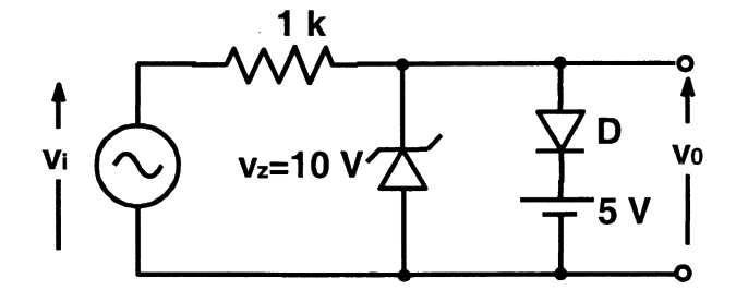
The equivalent circuits of a diode, during forward biased and reverse biased conditions, are shown in the figure. If such a diode is used in clipper circuit of figure given above, the output voltage ($v_o$) of the circuit will be
Open complete paper
5
2008 · Electrical Engineering · Analog and Digital Electronics · Diodes, Amplifiers and Operational Amplifiers
Electrical Engineering (EE) 2008
Two perfectly matched silicon transistors are connected as shown in the figure. Assuming the \( \beta \) of the transistors to be very high and the forward voltage drop in diodes to be 0.7V, the value of current I is
Open complete paper
6
2008 · Electrical Engineering · Analog and Digital Electronics · Diodes, Amplifiers and Operational Amplifiers
Electrical Engineering (EE) 2008
In the voltage doubler circuit shown in the figure, the switch ‘S’ is closed at \( t = 0 \). Assuming diodes \( D_1 \) and \( D_2 \) to be ideal, load resistance to be infinite and initial capacitor voltages to be zero, the steady state voltage across capacitors \( C_1 \) and \( C_2 \) will be
Open complete paper
7
2008 · Electrical Engineering · Analog and Digital Electronics · Diodes, Amplifiers and Operational Amplifiers
Electrical Engineering (EE) 2008

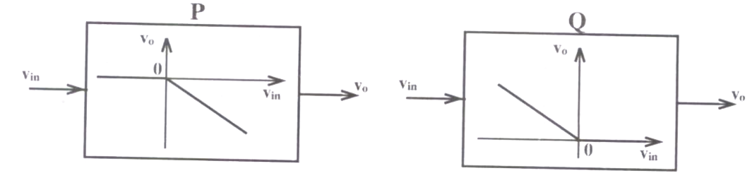
The block diagrams of two types of half wave rectifiers are shown in the figure. The transfer characteristics of the rectifiers are also shown within the block. It is desired to make full wave rectifier using above two half-wave rectifiers. The resultant circuit will be

Question diagram

Open complete paper
8
2009 · Electrical Engineering · Analog and Digital Electronics · Diodes, Amplifiers and Operational Amplifiers
Electrical Engineering (EE) 2009

The nature of feedback in the opamp circuit shown is

Question diagram

Open complete paper
9
2009 · Electrical Engineering · Analog and Digital Electronics · Diodes, Amplifiers and Operational Amplifiers
Electrical Engineering (EE) 2009
Transformer and emitter follower can both be used for impedance matching at the output of an audio amplifier. The basic relationship between the input power \(P_{in}\) and output power \(P_{out}\) in both the cases is
Open complete paper
10
2009 · Electrical Engineering · Analog and Digital Electronics · Diodes, Amplifiers and Operational Amplifiers
Electrical Engineering (EE) 2009

The equivalent capacitance of the input loop of the circuit shown is

Question diagram

Open complete paper
11
2009 · Electrical Engineering · Analog and Digital Electronics · Diodes, Amplifiers and Operational Amplifiers
Electrical Engineering (EE) 2009

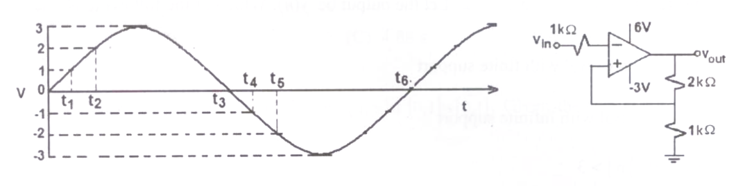
An ideal opamp circuit and its input waveform are shown in the figures. The output waveform of this circuit will be

Question diagram

Open complete paper
12
2010 · Electrical Engineering · Analog and Digital Electronics · Diodes, Amplifiers and Operational Amplifiers
Electrical Engineering (EE) 2010
Given that the op-amp is ideal, the output voltage V_0 is
Open complete paper
13
2010 · Electrical Engineering · Analog and Digital Electronics · Diodes, Amplifiers and Operational Amplifiers
Electrical Engineering (EE) 2010
Assuming that the diodes in the given circuit are ideal, the voltage V_0 is
Open complete paper
14
2010 · Electrical Engineering · Analog and Digital Electronics · Diodes, Amplifiers and Operational Amplifiers
Electrical Engineering (EE) 2010
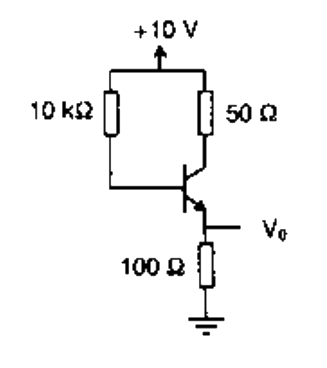
The transistor circuit shown uses a silicon transistor with VBE = 0.7 V, IC = IE and a dc current gain of 100. The value of VE is

Question diagram

Open complete paper
15
2011 · Electrical Engineering · Analog and Digital Electronics · Diodes, Amplifiers and Operational Amplifiers
Electrical Engineering (EE) 2011
The transistor used in the circuit shown below has a \(\beta\) of 30 and \(I_{CBO}\) is negligible. If the forward voltage drop of diode is 0.7 V, then the current through collector will be

Question diagram

Open complete paper
16
2011 · Electrical Engineering · Analog and Digital Electronics · Diodes, Amplifiers and Operational Amplifiers
Electrical Engineering (EE) 2011
A clipper circuit is shown below.
Assuming forward voltage drops of the diodes to be 0.7 V, the input-output transfer characteristics of the circuit is

Question diagram

Open complete paper
17
2012 · Electrical Engineering · Analog and Digital Electronics · Diodes, Amplifiers and Operational Amplifiers
Electrical Engineering (EE) 2012

The impedance looking into nodes 1 and 2 in the given circuit is

Question diagram

Open complete paper
18
2012 · Electrical Engineering · Analog and Digital Electronics · Diodes, Amplifiers and Operational Amplifiers
Electrical Engineering (EE) 2012
The i-v characteristics of the diode in the circuit given below are \[i = \begin{cases}\frac{v-0.7}{500} \text{ A}, & v \geq 0.7 \text{ V} \\ 0 \text{ A}, & v < 0.7 \text{ V}\end{cases}\] The current in the circuit is
Open complete paper
19
2012 · Electrical Engineering · Analog and Digital Electronics · Diodes, Amplifiers and Operational Amplifiers
Electrical Engineering (EE) 2012
The voltage gain A_v of the circuit shown below is
(A) |A_v| ≈ 200
(B) |A_v| ≈ 100
(C) |A_v| ≈ 20
(D) |A_v| ≈ 10

Question diagram

Open complete paper
20
2013 · Electrical Engineering · Analog and Digital Electronics · Diodes, Amplifiers and Operational Amplifiers
Electrical Engineering (EE) 2013 [Session 1]
In the circuit shown below what is the output voltage (Vout) in Volts if a silicon transistor Q and an ideal op-amp are used?
Open complete paper

Showing 20 of 78 questions