My Cart
Your Cart 0

    Your cart is empty.

  • Total (Amount) ₹0.00
Previous year question hub

System Modelling and Feedback - Control Systems - Electrical Engineering Previous Year Questions

Practice System Modelling and Feedback - Control Systems - Electrical Engineering previous year questions organised from real papers, with year-wise coverage and clear topic navigation.

16Papers
13Years
36Questions
1Topics

System Modelling and Feedback question pattern

Every graph below is calculated only from this selection.

Questions by year

Compare question counts across years.

Difficulty distribution

How the classified questions are distributed by difficulty.

Medium 24 66.7%
Easy 12 33.3%

Question type distribution

MCQ, numerical, multiple-select and other formats found in these papers.

MCQ 30 83.3%
Numerical Answer Type (NAT) 4 11.1%
MSQ 2 5.6%

Subject weightage

Top subjects by unique question coverage.

Electrical Engineering
36 Qs

Most asked topics

Top topics across the included previous year papers.

Control Systems
36 Qs

Subtopic coverage

Top subtopics inside this exact selection.

System Modelling and Feedback
36 Qs

Paper coverage

Question coverage for the most populated papers. Every active PYP paper remains listed below.

Electrical Engineering (EE) 2024
1 Qs
Electrical Engineering (EE) 2023
4 Qs
Electrical Engineering (EE) 2021
2 Qs
Electrical Engineering (EE) 2020
3 Qs
Electrical Engineering (EE) 2018
1 Qs
Electrical Engineering (EE) 2017 [Session 1]
1 Qs
Electrical Engineering (EE) 2016 [Session 2]
1 Qs
Electrical Engineering (EE) 2014 [Session 3]
1 Qs
Electrical Engineering (EE) 2013 [Session 4]
4 Qs
Electrical Engineering (EE) 2013 [Session 1]
3 Qs
Electrical Engineering (EE) 2013 [Session 2]
3 Qs
Electrical Engineering (EE) 2013 [Session 3]
3 Qs
Electrical Engineering (EE) 2011
2 Qs
Electrical Engineering (EE) 2010
2 Qs
Electrical Engineering (EE) 2008
3 Qs
Electrical Engineering (EE) 2007
2 Qs

Included previous year papers

Newest papers appear first. Search these papers or sort by year and name.

Paper nameYearPDFAttempt
Electrical Engineering (EE) 20242024
1 questions in this view
2024
Electrical Engineering (EE) 20232023
4 questions in this view
2023
Electrical Engineering (EE) 20212021
2 questions in this view
2021
Electrical Engineering (EE) 20202020
3 questions in this view
2020
Electrical Engineering (EE) 20182018
1 questions in this view
2018
Electrical Engineering (EE) 2017 [Session 1]2017
1 questions in this view
2017
Electrical Engineering (EE) 2016 [Session 2]2016
1 questions in this view
2016
Electrical Engineering (EE) 2014 [Session 3]2014
1 questions in this view
2014
Electrical Engineering (EE) 2013 [Session 1]2013
3 questions in this view
2013
Electrical Engineering (EE) 2013 [Session 2]2013
3 questions in this view
2013
Electrical Engineering (EE) 2013 [Session 3]2013
3 questions in this view
2013
Electrical Engineering (EE) 2013 [Session 4]2013
4 questions in this view
2013
Electrical Engineering (EE) 20112011
2 questions in this view
2011
Electrical Engineering (EE) 20102010
2 questions in this view
2010
Electrical Engineering (EE) 20082008
3 questions in this view
2008
Electrical Engineering (EE) 20072007
2 questions in this view
2007

All System Modelling and Feedback previous year questions

Practice every matching question in batches of 20, with every available option.

1
2007 · Electrical Engineering · Control Systems · System Modelling and Feedback
Electrical Engineering (EE) 2007
The system shown in figure below can be reduced to the form

with
Open complete paper
2
2007 · Electrical Engineering · Control Systems · System Modelling and Feedback
Electrical Engineering (EE) 2007
Consider the feedback control system shown below which is subjected to a unit step input. The system is stable and has the following parameters kp = 4, kI = 10, ω = 500 and ζ = 0.7.

The steady state value of z is
Open complete paper
3
2008 · Electrical Engineering · Control Systems · System Modelling and Feedback
Electrical Engineering (EE) 2008
The transfer functions of two compensators are given below:
C1 = 10(s+1)/(s+10), C2 = s+10/[10(s+1)]
Which one of the following statements is correct?
Open complete paper
4
2008 · Electrical Engineering · Control Systems · System Modelling and Feedback
Electrical Engineering (EE) 2008
The transfer function G(s) of this system will be
Open complete paper
5
2008 · Electrical Engineering · Control Systems · System Modelling and Feedback
Electrical Engineering (EE) 2008
A unity feedback is provided to the above system G(s) to make it a closed loop system as shown in figure.
For a unit step input r(t), the steady state error in the output will be

Question diagram

Open complete paper
6
2010 · Electrical Engineering · Control Systems · System Modelling and Feedback
Electrical Engineering (EE) 2010

As shown in the figure, a negative feedback system has an amplifier of gain 100 with ±10% tolerance in the forward path, and an attenuator of value 9/100 in the feedback path. The overall system gain is approximately:

Question diagram

Open complete paper
7
2010 · Electrical Engineering · Control Systems · System Modelling and Feedback
Electrical Engineering (EE) 2010

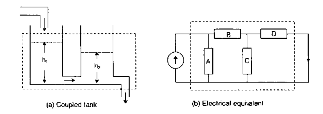
If the electrical circuit of figure (b) is an equivalent of the coupled tank system of figure (a), then

Question diagram

Open complete paper
8
2011 · Electrical Engineering · Control Systems · System Modelling and Feedback
Electrical Engineering (EE) 2011
An open loop system represented by the transfer function \(G(s) = \frac{(s-1)}{(s+2)(s+3)}\) is
Open complete paper
9
2011 · Electrical Engineering · Control Systems · System Modelling and Feedback
Electrical Engineering (EE) 2011
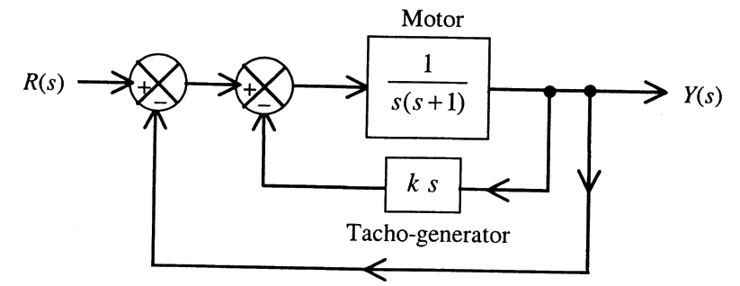
A two-loop position control system is shown below. The gain \(k\) of the Tacho-generator influences mainly the

Question diagram

Open complete paper
10
2013 · Electrical Engineering · Control Systems · System Modelling and Feedback
Electrical Engineering (EE) 2013 [Session 1]
Assuming zero initial condition, the response y(t) of the system given below to a unit step input u(t) is
Open complete paper
11
2013 · Electrical Engineering · Control Systems · System Modelling and Feedback
Electrical Engineering (EE) 2013 [Session 1]
The open-loop transfer function of a dc motor is given as \(\frac{\omega(s)}{V_a(s)} = \frac{10}{1+10s}\). When connected in feedback as shown below, the approximate value of Ka that will reduce the time constant of the closed loop system by one hundred times as compared to that of the open-loop system is
Open complete paper
12
2013 · Electrical Engineering · Control Systems · System Modelling and Feedback
Electrical Engineering (EE) 2013 [Session 1]
The signal flow graph for a system is given below. The transfer function \( \frac{Y(s)}{U(s)} \) for this system is
Open complete paper
13
2013 · Electrical Engineering · Control Systems · System Modelling and Feedback
Electrical Engineering (EE) 2013 [Session 2]
In the feedback network shown below, if the feedback factor k is increased, then the
Open complete paper
14
2013 · Electrical Engineering · Control Systems · System Modelling and Feedback
Electrical Engineering (EE) 2013 [Session 2]
The open-loop transfer function of a dc motor is given as \( \frac{\omega(s)}{V_a(s)} = \frac{10}{1+10s} \). When connected in feedback as shown below, the approximate value of \( K_a \) that will reduce the time constant of the closed loop system by one hundred times as compared to that of the open-loop system is
Open complete paper
15
2013 · Electrical Engineering · Control Systems · System Modelling and Feedback
Electrical Engineering (EE) 2013 [Session 3]
Assuming zero initial condition, the response \(y(t)\) of the system given below to a unit step input \(u(t)\) is
Open complete paper
16
2013 · Electrical Engineering · Control Systems · System Modelling and Feedback
Electrical Engineering (EE) 2013 [Session 3]
The open-loop transfer function of a dc motor is given as \(\frac{\omega(s)}{V_a(s)}=\frac{10}{1+10s}\) . When connected in feedback as shown below, the approximate value of \(K_a\) that will reduce the time constant of the closed loop system by one hundred times as compared to that of the open-loop system is
Open complete paper
17
2013 · Electrical Engineering · Control Systems · System Modelling and Feedback
Electrical Engineering (EE) 2013 [Session 3]
The signal flow graph for a system is given below. The transfer function \(\frac{Y(s)}{U(s)}\) for this system is
Open complete paper
18
2013 · Electrical Engineering · Control Systems · System Modelling and Feedback
Electrical Engineering (EE) 2013 [Session 4]
The open-loop transfer function of a dc motor is given as \(\frac{\omega(s)}{V_a(s)} = \frac{10}{1+10s}\). When connected in feedback as shown below, the approximate value of \(K_a\) that will reduce the time constant of the closed loop system by one hundred times as compared to that of the open-loop system is
Open complete paper
19
2014 · Electrical Engineering · Control Systems · System Modelling and Feedback
Electrical Engineering (EE) 2014 [Session 3]
The signal flow graph of a system is shown below. U(s) is the input and C(s) is the output.
Assuming, \( h_1 = b_1 \) and \( h_0 = b_0 - b_1 a_1 \), the input-output transfer function, \( G(s) = \frac{C(s)}{U(s)} \) of the system is given by
Open complete paper
20
2016 · Electrical Engineering · Control Systems · System Modelling and Feedback
Electrical Engineering (EE) 2016 [Session 2]
A second-order real system has the following properties:
a) the damping ratio \(\zeta = 0.5\) and undamped natural frequency \(\omega_n = 10\) rad/s,
b) the steady state value of the output, to a unit step input, is 1.02.
The transfer function of the system is
Open complete paper

Showing 20 of 32 questions