My Cart
Your Cart 0

    Your cart is empty.

  • Total (Amount) ₹0.00
Previous year question hub

Fault Analysis and Protection - Power Systems - Electrical Engineering Previous Year Questions

Practice Fault Analysis and Protection - Power Systems - Electrical Engineering previous year questions organised from real papers, with year-wise coverage and clear topic navigation.

23Papers
18Years
40Questions
1Topics

Fault Analysis and Protection question pattern

Every graph below is calculated only from this selection.

Questions by year

Year-wise coverage for Fault Analysis and Protection. Each bar uses a separate theme-derived color.

Difficulty distribution

How the classified questions are distributed by difficulty.

Medium 30 75%
Easy 7 17.5%
Hard 3 7.5%
Question type distribution

MCQ, numerical, multiple-select and other formats found in these papers.

MCQ 26 65%
Numerical Answer Type (NAT) 12 30%
MSQ 2 5%

Subject weightage

Top subjects by unique question coverage.

Electrical Engineering
40 Qs

Most asked topics

Top topics across the included previous year papers.

Power Systems
40 Qs

Subtopic coverage

Top subtopics inside this exact selection.

Fault Analysis and Protection
40 Qs

Paper coverage

Question coverage for the most populated papers. Every active PYP paper remains listed below.

Electrical Engineering (EE) 2025
1 Qs
Electrical Engineering (EE) 2024
1 Qs
Electrical Engineering (EE) 2023
2 Qs
Electrical Engineering (EE) 2022
1 Qs
Electrical Engineering (EE) 2021
2 Qs
Electrical Engineering (EE) 2020
1 Qs
Electrical Engineering (EE) 2019
3 Qs
Electrical Engineering (EE) 2018
2 Qs
Electrical Engineering (EE) 2017 [Session 1]
1 Qs
Electrical Engineering (EE) 2016 [Session 1]
2 Qs
Electrical Engineering (EE) 2016 [Session 2]
2 Qs
Electrical Engineering (EE) 2014 [Session 1]
4 Qs
Electrical Engineering (EE) 2014 [Session 2]
1 Qs
Electrical Engineering (EE) 2013 [Session 1]
1 Qs
Electrical Engineering (EE) 2013 [Session 2]
1 Qs
Electrical Engineering (EE) 2013 [Session 3]
1 Qs
Electrical Engineering (EE) 2013 [Session 4]
1 Qs
Electrical Engineering (EE) 2012
1 Qs
Electrical Engineering (EE) 2011
3 Qs
Electrical Engineering (EE) 2010
2 Qs
Electrical Engineering (EE) 2009
1 Qs
Electrical Engineering (EE) 2008
5 Qs
Electrical Engineering (EE) 2007
1 Qs

Included previous year papers

Newest papers appear first. Sort by year, question coverage or name.

PaperYear / sessionQuestions in this viewOpen
Electrical Engineering (EE) 202520251View paper
Electrical Engineering (EE) 202420241View paper
Electrical Engineering (EE) 202320232View paper
Electrical Engineering (EE) 202220221View paper
Electrical Engineering (EE) 202120212View paper
Electrical Engineering (EE) 202020201View paper
Electrical Engineering (EE) 201920193View paper
Electrical Engineering (EE) 201820182View paper
Electrical Engineering (EE) 2017 [Session 1]20171View paper
Electrical Engineering (EE) 2016 [Session 1]20162View paper
Electrical Engineering (EE) 2016 [Session 2]20162View paper
Electrical Engineering (EE) 2014 [Session 1]20144View paper
Electrical Engineering (EE) 2014 [Session 2]20141View paper
Electrical Engineering (EE) 2013 [Session 1]20131View paper
Electrical Engineering (EE) 2013 [Session 2]20131View paper
Electrical Engineering (EE) 2013 [Session 3]20131View paper
Electrical Engineering (EE) 2013 [Session 4]20131View paper
Electrical Engineering (EE) 201220121View paper
Electrical Engineering (EE) 201120113View paper
Electrical Engineering (EE) 201020102View paper
Electrical Engineering (EE) 200920091View paper
Electrical Engineering (EE) 200820085View paper
Electrical Engineering (EE) 200720071View paper

All Fault Analysis and Protection previous year questions

Practice every matching question in batches of 20, with every available option.

1
2007 · Electrical Engineering · Power Systems · Fault Analysis and Protection
Electrical Engineering (EE) 2007

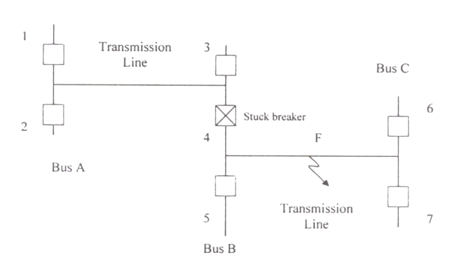
Consider the protection system shown in the figure below. The circuit breakers, numbered from 1 to 7 are of identical type. A single line to ground fault with zero fault impedance occurs at the midpoint of the line (at point F), but circuit breaker 4 fails to operate ("stuck breaker"). If the relays are coordinated correctly, a valid sequence of circuit breaker operations is

Question diagram

Open complete paper
2
2008 · Electrical Engineering · Power Systems · Fault Analysis and Protection
Electrical Engineering (EE) 2008
A two machine power system is shown below. Transmission line XY has positive sequence impedance of $Z_1 \, \Omega$ and zero sequence impedance of $Z_0 \, \Omega$. An 'a' phase to ground fault with zero fault impedance occurs at the centre of the transmission line. Bus voltage at X and line current from X to F for the phase 'a', are given by $V_a$ Volts and $I_a$ Amperes, respectively. Then, the impedance measured by the ground distance relay located at the terminal X of line XY will be given by
Open complete paper
3
2008 · Electrical Engineering · Power Systems · Fault Analysis and Protection
Electrical Engineering (EE) 2008
Voltage phasors at the two terminals of a transmission line of length 70 km have a magnitude of 1.0 per unit but are 180 degrees out of phase. Assuming that the maximum load current in the line is \(1/5^{th}\) of minimum 3-phase fault current, which one of the following transmission line protection schemes will NOT pick up for this condition?
Open complete paper
4
2008 · Electrical Engineering · Power Systems · Fault Analysis and Protection
Electrical Engineering (EE) 2008
The instant (t0) of the fault will be
Open complete paper
5
2008 · Electrical Engineering · Power Systems · Fault Analysis and Protection
Electrical Engineering (EE) 2008
The rms value of the ac component of fault current (IX) will be
Open complete paper
6
2008 · Electrical Engineering · Power Systems · Fault Analysis and Protection
Electrical Engineering (EE) 2008
Instead of the three phase fault, if a single line to ground fault occurs on phase 'a' at point 'F' with zero fault impedance, then the rms value of the ac component of fault current (IX) for phase 'a' will be
Open complete paper
7
2009 · Electrical Engineering · Power Systems · Fault Analysis and Protection
Electrical Engineering (EE) 2009
Match the items in List-I with the items in List-II and select the correct answer using the codes given below the lists.

List I Type of transmission lineList II Type of distance relay preferred
a. Short Line1. Ohm Relay
b. Medium Line2. Reactance Relay
c. Long Line3. Mho Relay
Open complete paper
8
2010 · Electrical Engineering · Power Systems · Fault Analysis and Protection
Electrical Engineering (EE) 2010

A three-phase, 33 kV oil circuit breaker is rated 1200 A, 2000 MVA, 3 s. The symmetrical breaking current is

Open complete paper
9
2010 · Electrical Engineering · Power Systems · Fault Analysis and Protection
Electrical Engineering (EE) 2010
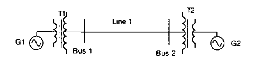
For the power system shown in the figure below, the specifications of the components are the following:
G1: 25 kV, 100 MVA, X = 9%
G2: 25 kV, 100 MVA, X = 9%
T1: 25 kV/220 kV, 90 MVA, X = 12%
T2: 220 kV/25 kV, 90 MVA, X = 12%
Line 1: 220 kV, X = 150 ohms
Choose 25 kV as the base voltage at the generator G1, and 200 MVA as the MVA base. The impedance diagram is

Question diagram

Open complete paper
10
2011 · Electrical Engineering · Power Systems · Fault Analysis and Protection
Electrical Engineering (EE) 2011

A negative sequence relay is commonly used to protect

Open complete paper
11
2011 · Electrical Engineering · Power Systems · Fault Analysis and Protection
Electrical Engineering (EE) 2011
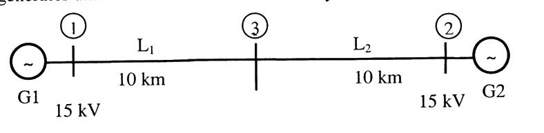
For the above system, the positive sequence diagram with the p.u values on the 100 MVA common base is

Question diagram

Open complete paper
12
2011 · Electrical Engineering · Power Systems · Fault Analysis and Protection
Electrical Engineering (EE) 2011

In the above system, the three-phase fault MVA at the bus 3 is

Open complete paper
13
2012 · Electrical Engineering · Power Systems · Fault Analysis and Protection
Electrical Engineering (EE) 2012
The sequence components of the fault current are as follows: I_positive = j1.5 pu, I_negative = -j0.5 pu, I_zero = -j1 pu. The type of fault in the system is
(A) LG
(B) LL
(C) LLG
(D) LLLG
Open complete paper
14
2013 · Electrical Engineering · Power Systems · Fault Analysis and Protection
Electrical Engineering (EE) 2013 [Session 1]
For a power system network with $n$ nodes, $Z_{33}$ of its bus impedance matrix is $j0.5$ per unit. The voltage at node 3 is $1.3\angle -10^{\circ}$ per unit. If a capacitor having reactance of $-j3.5$ per unit is now added to the network between node 3 and the reference node, the current drawn by the capacitor per unit is
Open complete paper
15
2013 · Electrical Engineering · Power Systems · Fault Analysis and Protection
Electrical Engineering (EE) 2013 [Session 2]
For a power system network with n nodes, Z_33 of its bus impedance matrix is j0.5 per unit. The voltage at node 3 is 1.3 ∠ -10° per unit. If a capacitor having reactance of -j3.5 per unit is now added to the network between node 3 and the reference node, the current drawn by the capacitor per unit is
Open complete paper
16
2013 · Electrical Engineering · Power Systems · Fault Analysis and Protection
Electrical Engineering (EE) 2013 [Session 3]
For a power system network with n nodes, \(Z_{33}\) of its bus impedance matrix is \(j0.5\) per unit. The voltage at node 3 is \(1.3\angle-10^\circ\) per unit. If a capacitor having reactance of \(-j3.5\) per unit is now added to the network between node 3 and the reference node, the current drawn by the capacitor per unit is
Open complete paper
17
2013 · Electrical Engineering · Power Systems · Fault Analysis and Protection
Electrical Engineering (EE) 2013 [Session 4]
For a power system network with n nodes, \(Z_{33}\) of its bus impedance matrix is j0.5 per unit. The voltage at node 3 is \(1.3 \angle -10^\circ\) per unit. If a capacitor having reactance of -j3.5 per unit is now added to the network between node 3 and the reference node, the current drawn by the capacitor per unit is
Open complete paper
18
2014 · Electrical Engineering · Power Systems · Fault Analysis and Protection
Electrical Engineering (EE) 2014 [Session 1]
Three-phase to ground fault takes place at locations $F_1$ and $F_2$ in the system shown in the figure.
If the fault takes place at location $F_1$, then the voltage and the current at bus A are $V_{F1}$ and $I_{F1}$ respectively. If the fault takes place at location $F_2$, then the voltage and the current at bus A are $V_{F2}$ and $I_{F2}$ respectively. The correct statement about voltages and currents during faults at $F_1$ and $F_2$ is
Open complete paper
19
2014 · Electrical Engineering · Power Systems · Fault Analysis and Protection
Electrical Engineering (EE) 2014 [Session 1]
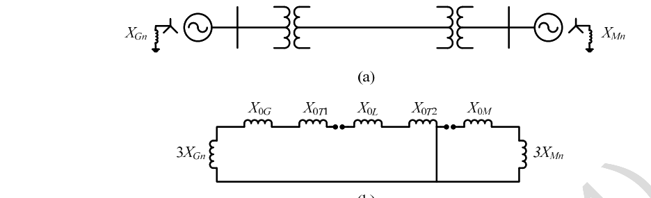
A 2-bus system and corresponding zero sequence network are shown in the figure.

The transformers T1 and T2 are connected as

Question diagram

Open complete paper
20
2014 · Electrical Engineering · Power Systems · Fault Analysis and Protection
Electrical Engineering (EE) 2014 [Session 1]
In an unbalanced three phase system, phase current \(I_a = 1\angle(-90°)\) pu, negative sequence current \(I_{b2} = 4\angle(-150°)\) pu, zero sequence current \(I_{c0} = 3\angle90°\) pu. The magnitude of phase current \(I_b\) in pu is
Open complete paper

Showing 20 of 40 questions