My Cart
Your Cart 0

    Your cart is empty.

  • Total (Amount) ₹0.00
Previous year question hub

DC-DC Converters - Power Electronics - Electrical Engineering Previous Year Questions

Practice DC-DC Converters - Power Electronics - Electrical Engineering previous year questions organised from real papers, with year-wise coverage and clear topic navigation.

21Papers
15Years
33Questions
1Topics

DC-DC Converters question pattern

Every graph below is calculated only from this selection.

Questions by year

Year-wise coverage for DC-DC Converters. Each bar uses a separate theme-derived color.

Difficulty distribution

How the classified questions are distributed by difficulty.

Medium 27 81.8%
Easy 5 15.2%
Hard 1 3%
Question type distribution

MCQ, numerical, multiple-select and other formats found in these papers.

MCQ 16 48.5%
Numerical Answer Type (NAT) 15 45.5%
MSQ 2 6.1%

Subject weightage

Top subjects by unique question coverage.

Electrical Engineering
33 Qs

Most asked topics

Top topics across the included previous year papers.

Power Electronics
33 Qs

Subtopic coverage

Top subtopics inside this exact selection.

DC-DC Converters
33 Qs

Paper coverage

Question coverage for the most populated papers. Every active PYP paper remains listed below.

Electrical Engineering (EE) 2025
1 Qs
Electrical Engineering (EE) 2024
1 Qs
Electrical Engineering (EE) 2023
1 Qs
Electrical Engineering (EE) 2022
1 Qs
Electrical Engineering (EE) 2021
2 Qs
Electrical Engineering (EE) 2020
1 Qs
Electrical Engineering (EE) 2019
2 Qs
Electrical Engineering (EE) 2018
2 Qs
Electrical Engineering (EE) 2017 [Session 1]
1 Qs
Electrical Engineering (EE) 2017 [Session 2]
1 Qs
Electrical Engineering (EE) 2016 [Session 2]
2 Qs
Electrical Engineering (EE) 2016 [Session 1]
1 Qs
Electrical Engineering (EE) 2014 [Session 1]
1 Qs
Electrical Engineering (EE) 2014 [Session 2]
1 Qs
Electrical Engineering (EE) 2013 [Session 1]
3 Qs
Electrical Engineering (EE) 2013 [Session 2]
3 Qs
Electrical Engineering (EE) 2013 [Session 4]
3 Qs
Electrical Engineering (EE) 2013 [Session 3]
2 Qs
Electrical Engineering (EE) 2012
1 Qs
Electrical Engineering (EE) 2010
1 Qs
Electrical Engineering (EE) 2008
2 Qs

Included previous year papers

Newest papers appear first. Sort by year, question coverage or name.

PaperYear / sessionQuestions in this viewOpen
Electrical Engineering (EE) 202520251View paper
Electrical Engineering (EE) 202420241View paper
Electrical Engineering (EE) 202320231View paper
Electrical Engineering (EE) 202220221View paper
Electrical Engineering (EE) 202120212View paper
Electrical Engineering (EE) 202020201View paper
Electrical Engineering (EE) 201920192View paper
Electrical Engineering (EE) 201820182View paper
Electrical Engineering (EE) 2017 [Session 1]20171View paper
Electrical Engineering (EE) 2017 [Session 2]20171View paper
Electrical Engineering (EE) 2016 [Session 1]20161View paper
Electrical Engineering (EE) 2016 [Session 2]20162View paper
Electrical Engineering (EE) 2014 [Session 1]20141View paper
Electrical Engineering (EE) 2014 [Session 2]20141View paper
Electrical Engineering (EE) 2013 [Session 1]20133View paper
Electrical Engineering (EE) 2013 [Session 2]20133View paper
Electrical Engineering (EE) 2013 [Session 3]20132View paper
Electrical Engineering (EE) 2013 [Session 4]20133View paper
Electrical Engineering (EE) 201220121View paper
Electrical Engineering (EE) 201020101View paper
Electrical Engineering (EE) 200820082View paper

All DC-DC Converters previous year questions

Practice every matching question in batches of 20, with every available option.

1
2008 · Electrical Engineering · Power Electronics · DC-DC Converters
Electrical Engineering (EE) 2008

A 220 V, 20 A, 1000 rpm, separately excited dc motor has an armature resistance of 2.5 Ω. The motor is controlled by a step down chopper with a frequency of 1 kHz. The input dc voltage to the chopper is 250 V. The duty cycle of the chopper for the motor to operate at a speed of 600 rpm delivering the rated torque will be

Open complete paper
2
2008 · Electrical Engineering · Power Electronics · DC-DC Converters
Electrical Engineering (EE) 2008
In the circuit shown in the figure, the switch is operated at a duty cycle of 0.5. A large capacitor is connected across the load. The inductor current is assumed to be continuous.

The average voltage across the load and the average current through the diode will respectively be
Open complete paper
3
2010 · Electrical Engineering · Power Electronics · DC-DC Converters
Electrical Engineering (EE) 2010

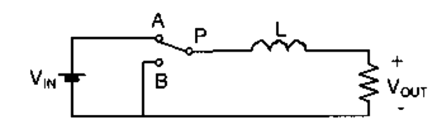
The power electronic converter shown in the figure has a single-pole double-throw switch. The pole P of the switch is connected alternately to throws A and B. The converter shown is a

Question diagram

Open complete paper
4
2012 · Electrical Engineering · Power Electronics · DC-DC Converters
Electrical Engineering (EE) 2012
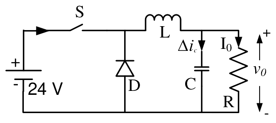
In the circuit shown, an ideal switch S is operated at 100 kHz with a duty ratio of 50 %. Given that Δi_c is 1.6 A peak-to-peak and I_0 is 5 A dc, the peak current in S is
(A) 6.6 A
(B) 5.0 A
(C) 5.8 A
(D) 4.2 A

Question diagram

Open complete paper
5
2013 · Electrical Engineering · Power Electronics · DC-DC Converters
Electrical Engineering (EE) 2013 [Session 1]
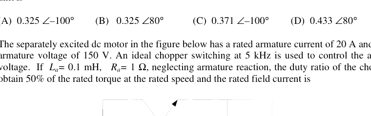
The separately excited dc motor in the figure below has a rated armature current of 20 A and a rated armature voltage of 150 V. An ideal chopper switching at 5 kHz is used to control the armature voltage. If $L_a = 0.1$ mH, $R_a = 1\ \Omega$, neglecting armature reaction, the duty ratio of the chopper to obtain 50% of the rated torque at the rated speed and the rated field current is
Open complete paper
6
2013 · Electrical Engineering · Power Electronics · DC-DC Converters
Electrical Engineering (EE) 2013 [Session 1]
In the figure shown below, the chopper feeds a resistive load from a battery source. MOSFET Q is switched at 250 kHz, with a duty ratio of 0.4. All elements of the circuit are assumed to be ideal.
The average source current in Amps in steady-state is
Open complete paper
7
2013 · Electrical Engineering · Power Electronics · DC-DC Converters
Electrical Engineering (EE) 2013 [Session 1]

The PEAK-TO-PEAK source current ripple in Amps is

Open complete paper
8
2013 · Electrical Engineering · Power Electronics · DC-DC Converters
Electrical Engineering (EE) 2013 [Session 2]
The separately excited dc motor in the figure below has a rated armature current of 20 A and a rated armature voltage of 150 V. An ideal chopper switching at 5 kHz is used to control the armature voltage. If L_a = 0.1 mH, R_a = 1 Ω, neglecting armature reaction, the duty ratio of the chopper to obtain 50% of the rated torque at the rated speed and the rated field current is
Open complete paper
9
2013 · Electrical Engineering · Power Electronics · DC-DC Converters
Electrical Engineering (EE) 2013 [Session 2]
The average source current in Amps in steady-state is
Open complete paper
10
2013 · Electrical Engineering · Power Electronics · DC-DC Converters
Electrical Engineering (EE) 2013 [Session 4]
The separately excited dc motor in the figure below has a rated armature current of 20 A and a rated armature voltage of 150 V. An ideal chopper switching at 5 kHz is used to control the armature voltage. If \(L_a = 0.1\) mH, \(R_a = 1\ \Omega\), neglecting armature reaction, the duty ratio of the chopper to obtain 50% of the rated torque at the rated speed and the rated field current is
\[\begin{figure}[h]\] \centering \includegraphics[width=0.5\textwidth]{Q41.png} \caption{Chopper circuit} \end{figure}

Question diagram

Open complete paper
11
2014 · Electrical Engineering · Power Electronics · DC-DC Converters
Electrical Engineering (EE) 2014 [Session 1]
Figure (i) shows the circuit diagram of a chopper. The switch S in the circuit in figure (i) is switched such that the voltage vD across the diode has the wave shape as shown in figure (ii). The capacitance C is large so that the voltage across it is constant. If switch S and the diode are ideal, the peak to peak ripple (in A) in the inductor current is ______
Open complete paper
12
2014 · Electrical Engineering · Power Electronics · DC-DC Converters
Electrical Engineering (EE) 2014 [Session 2]
A step-up chopper is used to feed a load at 400 V dc from a 250 V dc source. The inductor current is continuous. If the 'off' time of the switch is 20 \(\mu\)s, the switching frequency of the chopper in kHz is ______.
Open complete paper
13
2016 · Electrical Engineering · Power Electronics · DC-DC Converters
Electrical Engineering (EE) 2016 [Session 1]
A buck converter, as shown in Figure (a) below, is working in steady state. The output voltage and the inductor current can be assumed to be ripple free. Figure (b) shows the inductor voltage vL during a complete switching interval. Assuming all devices are ideal, the duty cycle of the buck converter is ______.
Open complete paper
14
2016 · Electrical Engineering · Power Electronics · DC-DC Converters
Electrical Engineering (EE) 2016 [Session 2]
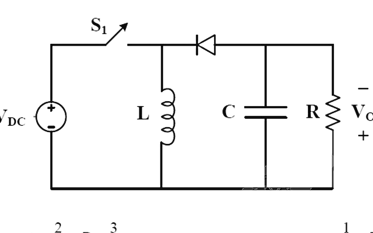
A buck-boost DC-DC converter, shown in the figure below, is used to convert 24 V battery voltage to 36 V DC voltage to feed a load of 72 W. It is operated at 20 kHz with an inductor of 2 mH and output capacitor of 1000 μF. All devices are considered to be ideal. The peak voltage across the solid-state switch (S), in volt, is ________.
Open complete paper
15
2016 · Electrical Engineering · Power Electronics · DC-DC Converters
Electrical Engineering (EE) 2016 [Session 2]
A DC-DC boost converter, as shown in the figure below, is used to boost 360V to 400 V, at a power of 4 kW. All devices are ideal. Considering continuous inductor current, the rms current in the solid state switch (S), in ampere, is ______.
Open complete paper
16
2017 · Electrical Engineering · Power Electronics · DC-DC Converters
Electrical Engineering (EE) 2017 [Session 1]

The input voltage VDC of the buck-boost converter shown below varies from 32 V to 72 V. Assume that all components are ideal, inductor current is continuous, and output voltage is ripple free. The range of duty ratio D of the converter for which the magnitude of the steady-state output voltage remains constant at 48 V is

Open complete paper
17
2017 · Electrical Engineering · Power Electronics · DC-DC Converters
Electrical Engineering (EE) 2017 [Session 2]
In the circuit shown all elements are ideal and the switch S is operated at 10 kHz and 60% duty ratio. The capacitor is large enough so that the ripple across it is negligible and at steady state acquires a voltage as shown. The peak current in amperes drawn from the 50 V DC source is __________. (Give the answer up to one decimal place.)

Question diagram

Open complete paper
18
2018 · Electrical Engineering · Power Electronics · DC-DC Converters
Electrical Engineering (EE) 2018
The figure shows two buck converters connected in parallel. The common input dc voltage for the converters has a value of 100 V. The converters have inductors of identical value. The load resistance is 1 \(\Omega\). The capacitor voltage has negligible ripple. Both converters operate in the continuous conduction mode. The switching frequency is 1 kHz, and the switch control signals are as shown. The circuit operates in the steady state. Assuming that the converters share the load equally, the average value of \(i_{S1}\), the current of switch S1 (in Ampere), is ______ (up to 2 decimal places).
Open complete paper
19
2018 · Electrical Engineering · Power Electronics · DC-DC Converters
Electrical Engineering (EE) 2018

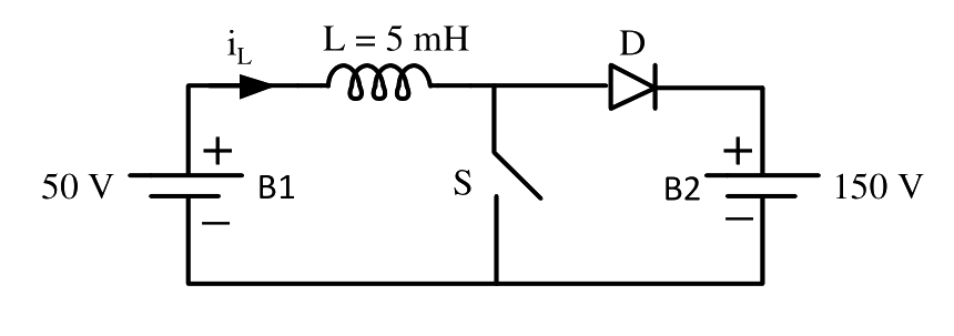
A dc to dc converter shown in the figure is charging a battery bank, B2 whose voltage is constant at 150 V. B1 is another battery bank whose voltage is constant at 50 V. The value of the inductor, L is 5 mH and the ideal switch, S is operated with a switching frequency of 5 kHz with a duty ratio of 0.4. Once the circuit has attained steady state and assuming the diode D to be ideal, the power transferred from B1 to B2 (in Watt) is ______ (up to 2 decimal places).

Question diagram

Open complete paper
20
2019 · Electrical Engineering · Power Electronics · DC-DC Converters
Electrical Engineering (EE) 2019
A DC-DC buck converter operates in continuous conduction mode. It has 48 V input voltage, and it feeds a resistive load of 24 $\Omega$. The switching frequency of the converter is 250 Hz. If switch-on duration is 1 ms, the load power is
Open complete paper

Showing 20 of 28 questions