My Cart
Your Cart 0

    Your cart is empty.

  • Total (Amount) ₹0.00
Previous year question hub

Controlled and Uncontrolled Rectifiers - Power Electronics - Electrical Engineering Previous Year Questions

Practice Controlled and Uncontrolled Rectifiers - Power Electronics - Electrical Engineering previous year questions organised from real papers, with year-wise coverage and clear topic navigation.

20Papers
16Years
52Questions
1Topics

Controlled and Uncontrolled Rectifiers question pattern

Every graph below is calculated only from this selection.

Questions by year

Year-wise coverage for Controlled and Uncontrolled Rectifiers. Each bar uses a separate theme-derived color.

Difficulty distribution

How the classified questions are distributed by difficulty.

Medium 40 76.9%
Easy 6 11.5%
Hard 6 11.5%
Question type distribution

MCQ, numerical, multiple-select and other formats found in these papers.

MCQ 32 61.5%
Numerical Answer Type (NAT) 20 38.5%

Subject weightage

Top subjects by unique question coverage.

Electrical Engineering
52 Qs

Most asked topics

Top topics across the included previous year papers.

Power Electronics
52 Qs

Subtopic coverage

Top subtopics inside this exact selection.

Controlled and Uncontrolled Rectifiers
52 Qs

Paper coverage

Question coverage for the most populated papers. Every active PYP paper remains listed below.

Electrical Engineering (EE) 2025
1 Qs
Electrical Engineering (EE) 2024
4 Qs
Electrical Engineering (EE) 2023
1 Qs
Electrical Engineering (EE) 2022
3 Qs
Electrical Engineering (EE) 2020
4 Qs
Electrical Engineering (EE) 2019
3 Qs
Electrical Engineering (EE) 2018
3 Qs
Electrical Engineering (EE) 2017 [Session 2]
4 Qs
Electrical Engineering (EE) 2017 [Session 1]
1 Qs
Electrical Engineering (EE) 2016 [Session 2]
2 Qs
Electrical Engineering (EE) 2016 [Session 1]
1 Qs
Electrical Engineering (EE) 2014 [Session 1]
2 Qs
Electrical Engineering (EE) 2014 [Session 2]
2 Qs
Electrical Engineering (EE) 2014 [Session 3]
1 Qs
Electrical Engineering (EE) 2012
1 Qs
Electrical Engineering (EE) 2011
4 Qs
Electrical Engineering (EE) 2010
2 Qs
Electrical Engineering (EE) 2009
1 Qs
Electrical Engineering (EE) 2008
6 Qs
Electrical Engineering (EE) 2007
6 Qs

Included previous year papers

Newest papers appear first. Sort by year, question coverage or name.

PaperYear / sessionQuestions in this viewOpen
Electrical Engineering (EE) 202520251View paper
Electrical Engineering (EE) 202420244View paper
Electrical Engineering (EE) 202320231View paper
Electrical Engineering (EE) 202220223View paper
Electrical Engineering (EE) 202020204View paper
Electrical Engineering (EE) 201920193View paper
Electrical Engineering (EE) 201820183View paper
Electrical Engineering (EE) 2017 [Session 1]20171View paper
Electrical Engineering (EE) 2017 [Session 2]20174View paper
Electrical Engineering (EE) 2016 [Session 1]20161View paper
Electrical Engineering (EE) 2016 [Session 2]20162View paper
Electrical Engineering (EE) 2014 [Session 1]20142View paper
Electrical Engineering (EE) 2014 [Session 2]20142View paper
Electrical Engineering (EE) 2014 [Session 3]20141View paper
Electrical Engineering (EE) 201220121View paper
Electrical Engineering (EE) 201120114View paper
Electrical Engineering (EE) 201020102View paper
Electrical Engineering (EE) 200920091View paper
Electrical Engineering (EE) 200820086View paper
Electrical Engineering (EE) 200720076View paper

All Controlled and Uncontrolled Rectifiers previous year questions

Practice every matching question in batches of 20, with every available option.

1
2007 · Electrical Engineering · Power Electronics · Controlled and Uncontrolled Rectifiers
Electrical Engineering (EE) 2007

A single-phase fully controlled thyristor bridge ac-dc converter is operating at a firing angle of 25° and an overlap angle of 10° with constant dc output current of 20 A. The fundamental power factor (displacement factor) at input ac mains is

Open complete paper
2
2007 · Electrical Engineering · Power Electronics · Controlled and Uncontrolled Rectifiers
Electrical Engineering (EE) 2007

A three-phase, fully-controlled thyristor bridge converter is used as line commutated inverter to feed 50 kW power at 420 V dc to a three-phase, 415 V (line), 50 Hz ac mains. Consider dc link current to be constant. The rms current of the thyristor is

Open complete paper
3
2007 · Electrical Engineering · Power Electronics · Controlled and Uncontrolled Rectifiers
Electrical Engineering (EE) 2007

A single phase full-wave half-controlled bridge converter feeds an inductive load. The two SCRs in the converter are connected to a common DC bus. The converter has to have a freewheeling diode

Open complete paper
4
2007 · Electrical Engineering · Power Electronics · Controlled and Uncontrolled Rectifiers
Electrical Engineering (EE) 2007
A three-phase, 440 V, 50 Hz ac mains fed thyristor bridge is feeding a 440 V dc, 15 kW, 1500 rpm separately excited dc motor with a ripple free continuous current in the dc link under all operating conditions. Neglecting the losses, the power factor of the ac mains at half the rated speed, is
Open complete paper
5
2007 · Electrical Engineering · Power Electronics · Controlled and Uncontrolled Rectifiers
Electrical Engineering (EE) 2007
A single-phase, 230 V, 50 Hz ac mains fed step down transformer (4:1) is supplying power to a half-wave uncontrolled ac-dc converter used for charging a battery (12 V dc) with the series current limiting resistor being 19.04 Ω. The charging current is
Open complete paper
6
2007 · Electrical Engineering · Power Electronics · Controlled and Uncontrolled Rectifiers
Electrical Engineering (EE) 2007

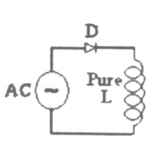
In the circuit of adjacent figure the diode connects the AC source to a pure inductance L. The diode conducts for

Question diagram

Open complete paper
7
2008 · Electrical Engineering · Power Electronics · Controlled and Uncontrolled Rectifiers
Electrical Engineering (EE) 2008
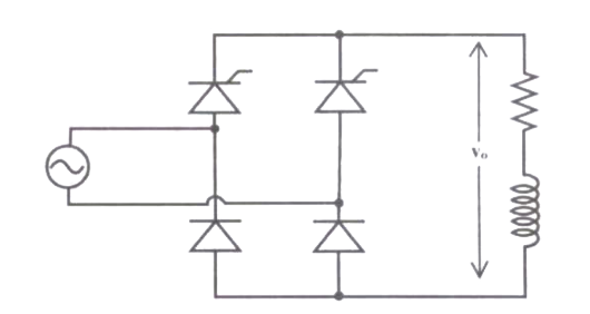
In the single phase voltage controller circuit shown in the figure, for what range of triggering angle (α), the output voltage (vo) is not controllable?
Open complete paper
8
2008 · Electrical Engineering · Power Electronics · Controlled and Uncontrolled Rectifiers
Electrical Engineering (EE) 2008
A single phase fully controlled bridge converter supplies a load drawing constant and ripple free load current. If the triggering angle is \(30^0\), the input power factor will be
Open complete paper
9
2008 · Electrical Engineering · Power Electronics · Controlled and Uncontrolled Rectifiers
Electrical Engineering (EE) 2008
A single-phase half controlled converter shown in the figure is feeding power to highly inductive load. The converter is operating at a firing angle of \(60^0\). [Image of circuit] If the firing pulses are suddenly removed, the steady state voltage (\(v_o\)) waveform of the converter will become

Question diagram

Open complete paper
10
2008 · Electrical Engineering · Power Electronics · Controlled and Uncontrolled Rectifiers
Electrical Engineering (EE) 2008

A 220 V, 1400 rpm, 40 A separately excited dc motor has an armature resistance of 0.4 Ω. The motor is fed from a single phase circulating current dual converter with an input ac line voltage of 220 V (rms). The approximate firing angles of the dual converter for motoring operation at 50% of rated torque and 1000 rpm will be

Open complete paper
11
2008 · Electrical Engineering · Power Electronics · Controlled and Uncontrolled Rectifiers
Electrical Engineering (EE) 2008
A single phase fully controlled converter bridge is used for electrical braking of a separately excited dc motor. The dc motor load is represented by an equivalent circuit as shown in the figure.

Assume that the load inductance is sufficient to ensure continuous and ripple free load current. The firing angle of the bridge for a load current of I0 = 10 A will be
Open complete paper
12
2008 · Electrical Engineering · Power Electronics · Controlled and Uncontrolled Rectifiers
Electrical Engineering (EE) 2008
A three phase fully controlled bridge converter is feeding a load drawing a constant and ripple free load current of 10 A at a firing angle of 30°. The approximate Total Harmonic Distortion (%THD) and the rms value of fundamental component of the input current will respectively be
Open complete paper
13
2009 · Electrical Engineering · Power Electronics · Controlled and Uncontrolled Rectifiers
Electrical Engineering (EE) 2009
The peak voltage across A and B, with S open is
Open complete paper
14
2010 · Electrical Engineering · Power Electronics · Controlled and Uncontrolled Rectifiers
Electrical Engineering (EE) 2010
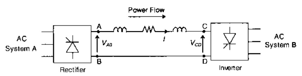
Power is transferred from system A to system B by an HVDC link as shown in the figure. If the voltages \( V_{AB} \) and \( V_{CD} \) are as indicated in the figure, and \( I > 0 \), then

Question diagram

Open complete paper
15
2010 · Electrical Engineering · Power Electronics · Controlled and Uncontrolled Rectifiers
Electrical Engineering (EE) 2010

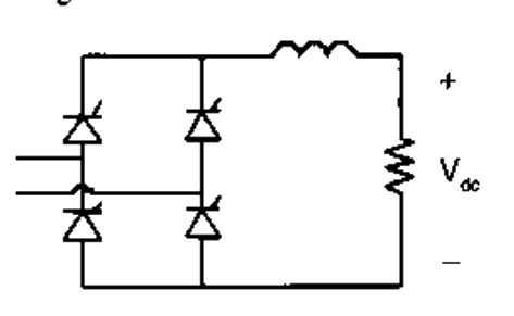
The fully controlled thyristor converter in the figure is fed from a single-phase source. When the firing angle is 0°, the dc output voltage of the converter is 300 V. What will be the output voltage for a firing angle of 60°, assuming continuous conduction?

Question diagram

Open complete paper
16
2011 · Electrical Engineering · Power Electronics · Controlled and Uncontrolled Rectifiers
Electrical Engineering (EE) 2011
The input power factor of the converter is
Open complete paper
17
2011 · Electrical Engineering · Power Electronics · Controlled and Uncontrolled Rectifiers
Electrical Engineering (EE) 2011
The active power drawn by the converter is
Open complete paper
18
2011 · Electrical Engineering · Power Electronics · Controlled and Uncontrolled Rectifiers
Electrical Engineering (EE) 2011
The maximum current through the battery will be

Question diagram

Open complete paper
19
2011 · Electrical Engineering · Power Electronics · Controlled and Uncontrolled Rectifiers
Electrical Engineering (EE) 2011

The kVA rating of the input transformer is

Open complete paper
20
2012 · Electrical Engineering · Power Electronics · Controlled and Uncontrolled Rectifiers
Electrical Engineering (EE) 2012
A half-controlled single-phase bridge rectifier is supplying an R-L load. It is operated at a firing angle α and the load current is continuous. The fraction of cycle that the freewheeling diode conducts is
(A) 1/2
(B) (1 - α/π)
(C) α/2π
(D) α/π
Open complete paper

Showing 20 of 52 questions