My Cart
Your Cart 0

    Your cart is empty.

  • Total (Amount) ₹0.00
Previous year question hub

Instrument Transformers and Digital Instruments - Electrical and Electronic Measurements - Electrical Engineering Previous Year Questions

Practice Instrument Transformers and Digital Instruments - Electrical and Electronic Measurements - Electrical Engineering previous year questions organised from real papers, with year-wise coverage and clear topic navigation.

15Papers
12Years
20Questions
1Topics

Instrument Transformers and Digital Instruments question pattern

Every graph below is calculated only from this selection.

Questions by year

Year-wise coverage for Instrument Transformers and Digital Instruments. Each bar uses a separate theme-derived color.

Difficulty distribution

How the classified questions are distributed by difficulty.

Medium 14 70%
Easy 6 30%

Question type distribution

MCQ, numerical, multiple-select and other formats found in these papers.

MCQ 16 80%
Numerical Answer Type (NAT) 4 20%

Subject weightage

Top subjects by unique question coverage.

Electrical Engineering
20 Qs

Most asked topics

Top topics across the included previous year papers.

Electrical and Electronic Measurements
20 Qs

Subtopic coverage

Top subtopics inside this exact selection.

Instrument Transformers and Digital Instruments
20 Qs

Paper coverage

Question coverage for the most populated papers. Every active PYP paper remains listed below.

Electrical Engineering (EE) 2024
1 Qs
Electrical Engineering (EE) 2020
1 Qs
Electrical Engineering (EE) 2019
2 Qs
Electrical Engineering (EE) 2017 [Session 2]
2 Qs
Electrical Engineering (EE) 2017 [Session 1]
1 Qs
Electrical Engineering (EE) 2014 [Session 1]
1 Qs
Electrical Engineering (EE) 2014 [Session 2]
1 Qs
Electrical Engineering (EE) 2013 [Session 3]
2 Qs
Electrical Engineering (EE) 2013 [Session 4]
2 Qs
Electrical Engineering (EE) 2012
1 Qs
Electrical Engineering (EE) 2011
1 Qs
Electrical Engineering (EE) 2010
1 Qs
Electrical Engineering (EE) 2009
1 Qs
Electrical Engineering (EE) 2008
2 Qs
Electrical Engineering (EE) 2007
1 Qs

Included previous year papers

Newest papers appear first. Sort by year, question coverage or name.

PaperYear / sessionQuestions in this viewOpen
Electrical Engineering (EE) 202420241View paper
Electrical Engineering (EE) 202020201View paper
Electrical Engineering (EE) 201920192View paper
Electrical Engineering (EE) 2017 [Session 1]20171View paper
Electrical Engineering (EE) 2017 [Session 2]20172View paper
Electrical Engineering (EE) 2014 [Session 1]20141View paper
Electrical Engineering (EE) 2014 [Session 2]20141View paper
Electrical Engineering (EE) 2013 [Session 3]20132View paper
Electrical Engineering (EE) 2013 [Session 4]20132View paper
Electrical Engineering (EE) 201220121View paper
Electrical Engineering (EE) 201120111View paper
Electrical Engineering (EE) 201020101View paper
Electrical Engineering (EE) 200920091View paper
Electrical Engineering (EE) 200820082View paper
Electrical Engineering (EE) 200720071View paper

All Instrument Transformers and Digital Instruments previous year questions

Practice every matching question in batches of 20, with every available option.

1
2007 · Electrical Engineering · Electrical and Electronic Measurements · Instrument Transformers and Digital Instruments
Electrical Engineering (EE) 2007
The probes of a non-isolated, two-channel oscilloscope are clipped to points A, B and C in the circuit of the adjacent figure. \(V_{in}\) is a square wave of a suitable low frequency. The display on \(Ch_1\) and \(Ch_2\) are as shown on the right. Then the "Signal" and "Ground" probes \(S_1\), \(G_1\) and \(S_2\), \(G_2\) of \(Ch_1\) and \(Ch_2\) respectively are connected to points:
Open complete paper
2
2008 · Electrical Engineering · Electrical and Electronic Measurements · Instrument Transformers and Digital Instruments
Electrical Engineering (EE) 2008
Two 8-bit ADCs, one of single slope integrating type and other of successive approximation type, take $T_A$ and $T_B$ times to convert 5 V analog input signal to equivalent digital output. If the input analog signal is reduced to 2.5V, the approximate time taken by the two ADCs will respectively, be
Open complete paper
3
2008 · Electrical Engineering · Electrical and Electronic Measurements · Instrument Transformers and Digital Instruments
Electrical Engineering (EE) 2008
Two sinusoidal signals p(ωt) = A sin ωt and q(ωt) are applied to X and Y inputs of a dual channel CRO. The Lissajous figure displayed on the screen is shown below:

The signal q(ω2t) will be represented as
Open complete paper
4
2009 · Electrical Engineering · Electrical and Electronic Measurements · Instrument Transformers and Digital Instruments
Electrical Engineering (EE) 2009

The two inputs of a CRO are fed with two stationary periodic signals. In the X-Y mode, the screen shows a figure which changes from ellipse to circle and back to ellipse with its major axis changing orientation slowly and repeatedly. The following inference can be made from this.

Open complete paper
5
2010 · Electrical Engineering · Electrical and Electronic Measurements · Instrument Transformers and Digital Instruments
Electrical Engineering (EE) 2010
An ammeter has a current range of 0 – 5 A, and its internal resistance is 0.2 Ω. In order to change the range to 0 – 25 A, we need to add a resistance of
Open complete paper
6
2011 · Electrical Engineering · Electrical and Electronic Measurements · Instrument Transformers and Digital Instruments
Electrical Engineering (EE) 2011

A dual trace oscilloscope is set to operate in the ALTERNATE mode. The control input of the multiplexer used in the y-circuit is fed with a signal having a frequency equal to

Open complete paper
7
2012 · Electrical Engineering · Electrical and Electronic Measurements · Instrument Transformers and Digital Instruments
Electrical Engineering (EE) 2012

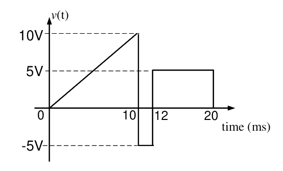
A periodic voltage waveform observed on an oscilloscope across a load is shown. A permanent magnet moving coil (PMMC) meter connected across the same load reads

Question diagram

Open complete paper
8
2013 · Electrical Engineering · Electrical and Electronic Measurements · Instrument Transformers and Digital Instruments
Electrical Engineering (EE) 2013 [Session 3]
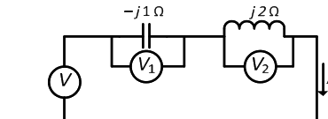
Three moving iron type voltmeters are connected as shown below. Voltmeter readings are \( V \), \( V_1 \) and \( V_2 \), as indicated. The correct relation among the voltmeter readings is

Question diagram

Open complete paper
9
2013 · Electrical Engineering · Electrical and Electronic Measurements · Instrument Transformers and Digital Instruments
Electrical Engineering (EE) 2013 [Session 3]
The input impedance of the permanent magnet moving coil (PMMC) voltmeter is infinite. Assuming that the diode shown in the figure below is ideal, the reading of the voltmeter in Volts is

Question diagram

Open complete paper
10
2013 · Electrical Engineering · Electrical and Electronic Measurements · Instrument Transformers and Digital Instruments
Electrical Engineering (EE) 2013 [Session 4]
Three moving iron type voltmeters are connected as shown below. Voltmeter readings are \( V, V_1 \) and \( V_2 \), as indicated. The correct relation among the voltmeter readings is

Question diagram

Open complete paper
11
2014 · Electrical Engineering · Electrical and Electronic Measurements · Instrument Transformers and Digital Instruments
Electrical Engineering (EE) 2014 [Session 1]
In an oscilloscope screen, linear sweep is applied at the
Open complete paper
12
2014 · Electrical Engineering · Electrical and Electronic Measurements · Instrument Transformers and Digital Instruments
Electrical Engineering (EE) 2014 [Session 2]
The saw-tooth voltage waveform shown in the figure is fed to a moving iron voltmeter. Its reading would be close to ______

Question diagram

Open complete paper
13
2017 · Electrical Engineering · Electrical and Electronic Measurements · Instrument Transformers and Digital Instruments
Electrical Engineering (EE) 2017 [Session 1]
The slope and level detector circuit in a CRO has a delay of 100 ns. The start-stop sweep generator has a response time of 50 ns. In order to display correctly, a delay line of
Open complete paper
14
2017 · Electrical Engineering · Electrical and Electronic Measurements · Instrument Transformers and Digital Instruments
Electrical Engineering (EE) 2017 [Session 2]
A stationary closed Lissajous pattern on an oscilloscope has 3 horizontal tangencies and 2 vertical tangencies for a horizontal input with frequency 3 kHz. The frequency of the vertical input is
Open complete paper
15
2017 · Electrical Engineering · Electrical and Electronic Measurements · Instrument Transformers and Digital Instruments
Electrical Engineering (EE) 2017 [Session 2]
A 10 ½ digit timer counter possesses a base clock of frequency 100 MHz. When measuring a particular input, the reading obtained is the same in: (i) Frequency mode of operation with a gating time of one second and (ii) Period mode of operation (in the x 10 ns scale). The frequency of the unknown input (reading obtained) in Hz is __________.
Open complete paper
16
2019 · Electrical Engineering · Electrical and Electronic Measurements · Instrument Transformers and Digital Instruments
Electrical Engineering (EE) 2019
The total impedance of the secondary winding, leads, and burden of a 5 A CT is 0.01 Ω. If the fault current is 20 times the rated primary current of the CT, the VA output of the CT is __________.
Open complete paper
17
2019 · Electrical Engineering · Electrical and Electronic Measurements · Instrument Transformers and Digital Instruments
Electrical Engineering (EE) 2019
A moving coil instrument having a resistance of \(10\ \Omega\), gives a full-scale deflection when the current is 10 mA. What should be the value of the series resistance, so that it can be used as a voltmeter for measuring potential difference up to 100 V?
Open complete paper
18
2020 · Electrical Engineering · Electrical and Electronic Measurements · Instrument Transformers and Digital Instruments
Electrical Engineering (EE) 2020
Currents through ammeters A2 and A3 in the figure are \(1\angle10^\circ\) and \(1\angle70^\circ\), respectively. The reading of the ammeter A1(rounded off to 3 decimal places) is ______ A.

Question diagram

Open complete paper
19
2024 · Electrical Engineering · Electrical and Electronic Measurements · Instrument Transformers and Digital Instruments
Electrical Engineering (EE) 2024
The table lists two instrument transformers and their features:
Instrument TransformersFeatures
P) Primary is connected in parallel to the grid
X) Current Transformer (CT)Q) Open circuited secondary is not desirable
Y) Potential Transformer (PT)R) Primary current is the line current
S) Secondary burden affects the primary current

The correct matching of the two columns is
Open complete paper