My Cart
Your Cart 0

    Your cart is empty.

  • Total (Amount) ₹0.00
Previous year question hub

Circuit Analysis - Networks, Signals and Systems - Electronics & Communication Engineering Previous Year Questions

Practice Circuit Analysis - Networks, Signals and Systems - Electronics & Communication Engineering previous year questions organised from real papers, with year-wise coverage and clear topic navigation.

20Papers
14Years
76Questions
1Topics

Circuit Analysis question pattern

Every graph below is calculated only from this selection.

Questions by year

Year-wise coverage for Circuit Analysis. Each bar uses a separate theme-derived color.

Difficulty distribution

How the classified questions are distributed by difficulty.

Medium 44 57.9%
Easy 26 34.2%
Hard 6 7.9%

Question type distribution

MCQ, numerical, multiple-select and other formats found in these papers.

MCQ 55 72.4%
Numerical Answer Type (NAT) 18 23.7%
Fill in the blanks 3 3.9%

Subject weightage

Top subjects by unique question coverage.

Electronics & Communication Engineering
76 Qs

Most asked topics

Top topics across the included previous year papers.

Networks, Signals and Systems
76 Qs

Subtopic coverage

Top subtopics inside this exact selection.

Circuit Analysis
76 Qs

Paper coverage

Question coverage for the most populated papers. Every active PYP paper remains listed below.

Electronics and Communication Engineering (EC) 2026
2 Qs
Electronics & Communication Engineering (EC) 2025
4 Qs
Electronics & Communication Engineering (EC) 2024
3 Qs
Electronics & Communication Engineering (EC) 2023
3 Qs
Electronics & Communication Engineering (EC) 2022
4 Qs
Electronics & Communication Engineering (EC) 2021
2 Qs
Electronics & Communication Engineering (EC) 2020
3 Qs
Electronics & Communication Engineering (EC) 2019
2 Qs
Electronics & Communication Engineering (EC) 2018
2 Qs
Electronics & Communication Engineering (EC) 2017
3 Qs
Electronics & Communication Engineering (EC) 2016 [Session 2]
2 Qs
Electronics & Communication Engineering (EC) 2016 [Session 3]
2 Qs
Electronics & Communication Engineering (EC) 2016 [Session 1]
1 Qs
Electronics & Communication Engineering (EC) 2014 [Session 4]
5 Qs
Electronics & Communication Engineering (EC) 2014 [Session 1]
4 Qs
Electronics & Communication Engineering (EC) 2013 [Session 2]
8 Qs
Electronics & Communication Engineering (EC) 2013 [Session 4]
7 Qs
Electronics & Communication Engineering (EC) 2013 [Session 1]
6 Qs
Electronics & Communication Engineering (EC) 2013 [Session 3]
6 Qs
Electronics & Communication Engineering (EC) 2012
7 Qs

Included previous year papers

Newest papers appear first. Sort by year, question coverage or name.

PaperYear / sessionQuestions in this viewOpen
Electronics and Communication Engineering (EC) 202620262View paper
Electronics & Communication Engineering (EC) 202520254View paper
Electronics & Communication Engineering (EC) 202420243View paper
Electronics & Communication Engineering (EC) 202320233View paper
Electronics & Communication Engineering (EC) 202220224View paper
Electronics & Communication Engineering (EC) 202120212View paper
Electronics & Communication Engineering (EC) 202020203View paper
Electronics & Communication Engineering (EC) 201920192View paper
Electronics & Communication Engineering (EC) 201820182View paper
Electronics & Communication Engineering (EC) 201720173View paper
Electronics & Communication Engineering (EC) 2016 [Session 1]20161View paper
Electronics & Communication Engineering (EC) 2016 [Session 2]20162View paper
Electronics & Communication Engineering (EC) 2016 [Session 3]20162View paper
Electronics & Communication Engineering (EC) 2014 [Session 1]20144View paper
Electronics & Communication Engineering (EC) 2014 [Session 4]20145View paper
Electronics & Communication Engineering (EC) 2013 [Session 1]20136View paper
Electronics & Communication Engineering (EC) 2013 [Session 2]20138View paper
Electronics & Communication Engineering (EC) 2013 [Session 3]20136View paper
Electronics & Communication Engineering (EC) 2013 [Session 4]20137View paper
Electronics & Communication Engineering (EC) 201220127View paper

All Circuit Analysis previous year questions

Practice every matching question in batches of 20, with every available option.

1
2012 · Electronics & Communication Engineering · Networks, Signals and Systems · Circuit Analysis
Electronics & Communication Engineering (EC) 2012
In the following figure, \(C_1\) and \(C_2\) are ideal capacitors. \(C_1\) has been charged to 12 V before the ideal switch S is closed at \(t = 0\). The current \(i(t)\) for all t is
Open complete paper
2
2012 · Electronics & Communication Engineering · Networks, Signals and Systems · Circuit Analysis
Electronics & Communication Engineering (EC) 2012

The impedance looking into nodes 1 and 2 in the given circuit is

Question diagram

Open complete paper
3
2012 · Electronics & Communication Engineering · Networks, Signals and Systems · Circuit Analysis
Electronics & Communication Engineering (EC) 2012

In the circuit shown below, the current through the inductor is

Question diagram

Open complete paper
4
2012 · Electronics & Communication Engineering · Networks, Signals and Systems · Circuit Analysis
Electronics & Communication Engineering (EC) 2012

Assuming both the voltage sources are in phase, the value of R for which maximum power is transferred from circuit A to circuit B is

Question diagram

Open complete paper
5
2012 · Electronics & Communication Engineering · Networks, Signals and Systems · Circuit Analysis
Electronics & Communication Engineering (EC) 2012
If \( V_A - V_B = 6 \) V, then \( V_C - V_D \) is

Question diagram

Open complete paper
6
2012 · Electronics & Communication Engineering · Networks, Signals and Systems · Circuit Analysis
Electronics & Communication Engineering (EC) 2012
With 10 V dc connected at port A, the current drawn by 7 Ω connected at port B is

Question diagram

Open complete paper
7
2012 · Electronics & Communication Engineering · Networks, Signals and Systems · Circuit Analysis
Electronics & Communication Engineering (EC) 2012

For the same network, with 6 V dc connected at port A, 1 Ω connected at port B draws 7/3 A. If 8 V dc is connected to port A, the open circuit voltage at port B is

Open complete paper
8
2013 · Electronics & Communication Engineering · Networks, Signals and Systems · Circuit Analysis
Electronics & Communication Engineering (EC) 2013 [Session 1]
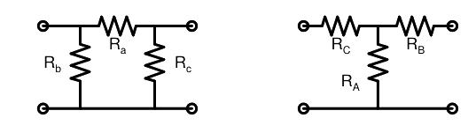
Consider a delta connection of resistors and its equivalent star connection as shown below. If all elements of the delta connection are scaled by a factor \( k, k>0 \), the elements of the corresponding star equivalent will be scaled by a factor of

Question diagram

Open complete paper
9
2013 · Electronics & Communication Engineering · Networks, Signals and Systems · Circuit Analysis
Electronics & Communication Engineering (EC) 2013 [Session 1]
The transfer function \( \frac{V_2(s)}{V_1(s)} \) of the circuit shown below is

Question diagram

Open complete paper
10
2013 · Electronics & Communication Engineering · Networks, Signals and Systems · Circuit Analysis
Electronics & Communication Engineering (EC) 2013 [Session 1]
A source \( v_s(t) = V \cos 100\pi t \) has an internal impedance of \( (4 + j3) \Omega \). If a purely resistive load connected to this source has to extract the maximum power out of the source, its value in \( \Omega \) should be
Open complete paper
11
2013 · Electronics & Communication Engineering · Networks, Signals and Systems · Circuit Analysis
Electronics & Communication Engineering (EC) 2013 [Session 1]
In the circuit shown below, if the source voltage \( V_S = 100 \angle 53.13^\circ V \) then the Thevenin’s equivalent voltage in Volts as seen by the load resistance \( R_L \) is

Question diagram

Open complete paper
12
2013 · Electronics & Communication Engineering · Networks, Signals and Systems · Circuit Analysis
Electronics & Communication Engineering (EC) 2013 [Session 1]
Two magnetically uncoupled inductive coils have \( Q \) factors \( q_1 \) and \( q_2 \) at the chosen operating frequency. Their respective resistances are \( R_1 \) and \( R_2 \). When connected in series, their effective \( Q \) factor at the same operating frequency is
Open complete paper
13
2013 · Electronics & Communication Engineering · Networks, Signals and Systems · Circuit Analysis
Electronics & Communication Engineering (EC) 2013 [Session 1]

The current in the 1Ω resistor in Amps is

Open complete paper
14
2013 · Electronics & Communication Engineering · Networks, Signals and Systems · Circuit Analysis
Electronics & Communication Engineering (EC) 2013 [Session 2]
The transfer function \(\frac{V_2(s)}{V_1(s)}\) of the circuit shown below is
Open complete paper
15
2013 · Electronics & Communication Engineering · Networks, Signals and Systems · Circuit Analysis
Electronics & Communication Engineering (EC) 2013 [Session 2]
A source \(v_s(t)=V\cos100\pi t\) has an internal impedance of \((4+j3)\Omega\). If a purely resistive load connected to this source has to extract the maximum power out of the source, its value in \(\Omega\) should be
Open complete paper
16
2013 · Electronics & Communication Engineering · Networks, Signals and Systems · Circuit Analysis
Electronics & Communication Engineering (EC) 2013 [Session 2]
Consider a delta connection of resistors and its equivalent star connection as shown below. If all elements of the delta connection are scaled by a factor $k, k>0$, the elements of the corresponding star equivalent will be scaled by a factor of

Question diagram

Open complete paper
17
2013 · Electronics & Communication Engineering · Networks, Signals and Systems · Circuit Analysis
Electronics & Communication Engineering (EC) 2013 [Session 2]
Three capacitors C₁, C₂ and C₃ whose values are 10μF, 5μF, and 2μF respectively, have breakdown voltages of 10V, 5V, and 2V respectively. For the interconnection shown below, the maximum safe voltage in Volts that can be applied across the combination, and the corresponding total charge in μC stored in the effective capacitance across the terminals are respectively,
Open complete paper
18
2013 · Electronics & Communication Engineering · Networks, Signals and Systems · Circuit Analysis
Electronics & Communication Engineering (EC) 2013 [Session 2]
In the circuit shown below, if the source voltage \(V_S = 100 \angle 53.13^\circ V\) then the Thevenin’s equivalent voltage in Volts as seen by the load resistance \(R_L\) is

Question diagram

Open complete paper
19
2013 · Electronics & Communication Engineering · Networks, Signals and Systems · Circuit Analysis
Electronics & Communication Engineering (EC) 2013 [Session 2]
Two magnetically uncoupled inductive coils have \(Q\) factors \(q_1\) and \(q_2\) at the chosen operating frequency. Their respective resistances are \(R_1\) and \(R_2\). When connected in series, their effective \(Q\) factor at the same operating frequency is
Open complete paper
20
2013 · Electronics & Communication Engineering · Networks, Signals and Systems · Circuit Analysis
Electronics & Communication Engineering (EC) 2013 [Session 2]
The current \(I_1\) in Amps in the voltage source, and voltage \(V_s\) in Volts across the current source respectively, are
Open complete paper

Showing 20 of 69 questions