My Cart
Your Cart 0

    Your cart is empty.

  • Total (Amount) ₹0.00
Previous year question hub

Power Generation and Transmission - Power Systems - Electrical Engineering Previous Year Questions

Practice Power Generation and Transmission - Power Systems - Electrical Engineering previous year questions organised from real papers, with year-wise coverage and clear topic navigation.

17Papers
14Years
33Questions
1Topics

Power Generation and Transmission question pattern

Every graph below is calculated only from this selection.

Questions by year

Year-wise coverage for Power Generation and Transmission. Each bar uses a separate theme-derived color.

Difficulty distribution

How the classified questions are distributed by difficulty.

Medium 24 72.7%
Easy 9 27.3%

Question type distribution

MCQ, numerical, multiple-select and other formats found in these papers.

MCQ 20 60.6%
Numerical Answer Type (NAT) 13 39.4%

Subject weightage

Top subjects by unique question coverage.

Electrical Engineering
33 Qs

Most asked topics

Top topics across the included previous year papers.

Power Systems
33 Qs

Subtopic coverage

Top subtopics inside this exact selection.

Power Generation and Transmission
33 Qs

Paper coverage

Question coverage for the most populated papers. Every active PYP paper remains listed below.

Electrical Engineering (EE) 2023
1 Qs
Electrical Engineering (EE) 2022
2 Qs
Electrical Engineering (EE) 2021
3 Qs
Electrical Engineering (EE) 2020
1 Qs
Electrical Engineering (EE) 2019
2 Qs
Electrical Engineering (EE) 2018
1 Qs
Electrical Engineering (EE) 2017 [Session 2]
4 Qs
Electrical Engineering (EE) 2016 [Session 1]
1 Qs
Electrical Engineering (EE) 2016 [Session 2]
1 Qs
Electrical Engineering (EE) 2014 [Session 2]
2 Qs
Electrical Engineering (EE) 2014 [Session 3]
2 Qs
Electrical Engineering (EE) 2014 [Session 1]
1 Qs
Electrical Engineering (EE) 2011
1 Qs
Electrical Engineering (EE) 2010
3 Qs
Electrical Engineering (EE) 2009
2 Qs
Electrical Engineering (EE) 2008
4 Qs
Electrical Engineering (EE) 2007
2 Qs

Included previous year papers

Newest papers appear first. Sort by year, question coverage or name.

PaperYear / sessionQuestions in this viewOpen
Electrical Engineering (EE) 202320231View paper
Electrical Engineering (EE) 202220222View paper
Electrical Engineering (EE) 202120213View paper
Electrical Engineering (EE) 202020201View paper
Electrical Engineering (EE) 201920192View paper
Electrical Engineering (EE) 201820181View paper
Electrical Engineering (EE) 2017 [Session 2]20174View paper
Electrical Engineering (EE) 2016 [Session 1]20161View paper
Electrical Engineering (EE) 2016 [Session 2]20161View paper
Electrical Engineering (EE) 2014 [Session 1]20141View paper
Electrical Engineering (EE) 2014 [Session 2]20142View paper
Electrical Engineering (EE) 2014 [Session 3]20142View paper
Electrical Engineering (EE) 201120111View paper
Electrical Engineering (EE) 201020103View paper
Electrical Engineering (EE) 200920092View paper
Electrical Engineering (EE) 200820084View paper
Electrical Engineering (EE) 200720072View paper

All Power Generation and Transmission previous year questions

Practice every matching question in batches of 20, with every available option.

1
2007 · Electrical Engineering · Power Systems · Power Generation and Transmission
Electrical Engineering (EE) 2007

Consider a bundled conductor of an overhead line, consisting of three identical sub-conductors placed at the corners of an equilateral triangle as shown in the figure. If we neglect the charges on the other phase conductors and ground, and assume that spacing between sub-conductors is much larger than their radius, the maximum electric field intensity is experienced at

Question diagram

Open complete paper
2
2007 · Electrical Engineering · Power Systems · Power Generation and Transmission
Electrical Engineering (EE) 2007
The total reactance and total susceptance of a lossless overhead EHV line, operating at 50 Hz, are given by 0.045 pu and 1.2 pu respectively. If the velocity of wave propagation is \(3 \times 10^5\) km/s, then the approximate length of the line is
Open complete paper
3
2008 · Electrical Engineering · Power Systems · Power Generation and Transmission
Electrical Engineering (EE) 2008

An extra high voltage transmission line of length 300 km can be approximated by a lossless line having propagation constant β = 0.00127 radians per km. Then the percentage ratio of line length to wavelength will be given by

Open complete paper
4
2008 · Electrical Engineering · Power Systems · Power Generation and Transmission
Electrical Engineering (EE) 2008
A 3-phase transmission line is shown in the figure: Voltage drop across the transmission line is given by the following equation: [ΔVa; ΔVb; ΔVc] = [Zs Zm Zm; Zm Zs Zm; Zm Zm Zs] [Ia; Ib; Ic]. Shunt capacitance of the line can be neglected. If the line has positive sequence impedance of 15 Ω and zero sequence impedance of 48 Ω, then the values of Zs and Zm will be
Open complete paper
5
2008 · Electrical Engineering · Power Systems · Power Generation and Transmission
Electrical Engineering (EE) 2008
A lossless transmission line having Surge Impedance Loading (SIL) of 2280 MW is provided with a uniformly distributed series capacitive compensation of 30 %. Then, SIL of the compensated transmission line will be
Open complete paper
6
2008 · Electrical Engineering · Power Systems · Power Generation and Transmission
Electrical Engineering (EE) 2008
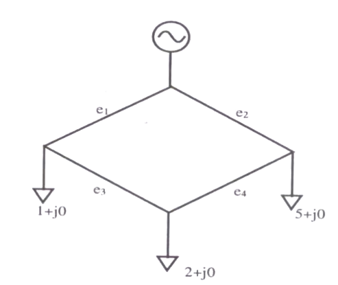
Single line diagram of a 4-bus single source distribution system is shown below. Branches \(e_1\), \(e_2\), \(e_3\) and \(e_4\) have equal impedances. The load current values indicated in the figure are in per unit. [Image of diagram] Distribution company's policy requires radial system operation with minimum loss. This can be achieved by opening of the branch

Question diagram

Open complete paper
7
2009 · Electrical Engineering · Power Systems · Power Generation and Transmission
Electrical Engineering (EE) 2009

Out of the following plant categories (i) Nuclear (ii) Run-of-river (iii) Pump Storage (iv) Diesel the base load power plants are

Open complete paper
8
2009 · Electrical Engineering · Power Systems · Power Generation and Transmission
Electrical Engineering (EE) 2009
For a fixed value of complex power flow in a transmission line having a sending end voltage \(V\), the real power loss will be proportional to
Open complete paper
9
2010 · Electrical Engineering · Power Systems · Power Generation and Transmission
Electrical Engineering (EE) 2010
Consider a step voltage of magnitude 1 pu travelling along a lossless transmission line that terminates in a reactor. The voltage magnitude across the reactor at the instant the travelling wave reaches the reactor is
Open complete paper
10
2010 · Electrical Engineering · Power Systems · Power Generation and Transmission
Electrical Engineering (EE) 2010

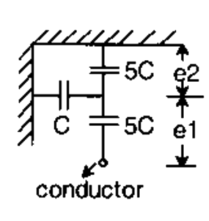
Consider a three-phase, 50 Hz, 11 kV distribution system. Each of the conductors is suspended by an insulator string having two identical porcelain insulators. The self capacitance of the insulator is 5 times the shunt capacitance between the link and the ground, as shown in the figure. The voltage across the two insulators are

Question diagram

Open complete paper
11
2010 · Electrical Engineering · Power Systems · Power Generation and Transmission
Electrical Engineering (EE) 2010

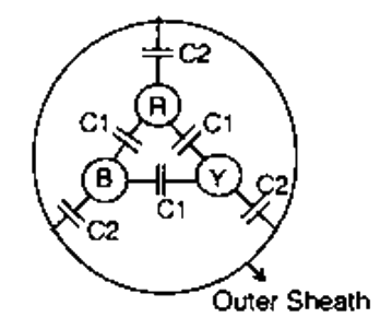
Consider a three-core, three-phase, 50 Hz, 11 kV cable whose conductors are denoted as R, Y and B in the figure. The inter-phase capacitance (C1) between each pair of conductors is 0.2 μF and the capacitance between each line conductor and the sheath is 0.4 μF. The per-phase charging current is

Question diagram

Open complete paper
12
2011 · Electrical Engineering · Power Systems · Power Generation and Transmission
Electrical Engineering (EE) 2011

A nuclear power station of 500 MW capacity is located at 300 km away from a load center. Select the most suitable power evacuation transmission configuration among the following options

Open complete paper
13
2014 · Electrical Engineering · Power Systems · Power Generation and Transmission
Electrical Engineering (EE) 2014 [Session 1]
A distribution feeder of 1 km length having resistance, but negligible reactance, is fed from both the ends by 400V, 50 Hz balanced sources. Both voltage sources S1 and S2 are in phase. The feeder supplies concentrated loads of unity power factor as shown in the figure.

The contributions of S1 and S2 in 100 A current supplied at location P respectively, are
Open complete paper
14
2014 · Electrical Engineering · Power Systems · Power Generation and Transmission
Electrical Engineering (EE) 2014 [Session 2]
A three phase star-connected load is drawing power at a voltage of 0.9 pu and 0.8 power factor lagging. The three phase base power and base current are 100 MVA and 437.38 A respectively. The line-to-line load voltage in kV is ______________.
Open complete paper
15
2014 · Electrical Engineering · Power Systems · Power Generation and Transmission
Electrical Engineering (EE) 2014 [Session 2]
The horizontally placed conductors of a single phase line operating at 50 Hz are having outside diameter of 1.6 cm, and the spacing between centers of the conductors is 6 m. The permittivity of free space is 8.854 × 10⁻¹² F/m. The capacitance to ground per kilometer of each line is
Open complete paper
16
2014 · Electrical Engineering · Power Systems · Power Generation and Transmission
Electrical Engineering (EE) 2014 [Session 3]
In a long transmission line with r, l, g and c are the resistance, inductance, shunt conductance and capacitance per unit length, respectively, the condition for distortionless transmission is
Open complete paper
17
2014 · Electrical Engineering · Power Systems · Power Generation and Transmission
Electrical Engineering (EE) 2014 [Session 3]
For a fully transposed transmission line
Open complete paper
18
2016 · Electrical Engineering · Power Systems · Power Generation and Transmission
Electrical Engineering (EE) 2016 [Session 1]
A single-phase transmission line has two conductors each of 10 mm radius. These are fixed at a center-to-center distance of 1 m in a horizontal plane. This is now converted to a three-phase transmission line by introducing a third conductor of the same radius. This conductor is fixed at an equal distance D from the two single-phase conductors. The three-phase line is fully transposed. The positive sequence inductance per phase of the three-phase system is to be 5% more than that of the inductance per conductor of the single-phase system. The distance D, in meters, is ________.
Open complete paper
19
2016 · Electrical Engineering · Power Systems · Power Generation and Transmission
Electrical Engineering (EE) 2016 [Session 2]
At no load condition, a 3-phase, 50 Hz, lossless power transmission line has sending-end and receiving-end voltages of 400 kV and 420 kV respectively. Assuming the velocity of traveling wave to be the velocity of light, the length of the line, in km, is ______.
Open complete paper
20
2017 · Electrical Engineering · Power Systems · Power Generation and Transmission
Electrical Engineering (EE) 2017 [Session 2]
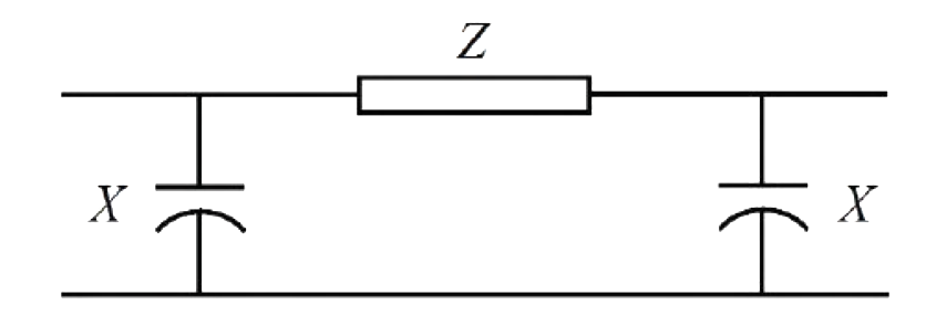
The nominal-$\pi$ circuit of a transmission line is shown in the figure. Impedance $Z = 100\angle80^\circ$ $\Omega$ and reactance $X = 3300$ $\Omega$. The magnitude of the characteristic impedance of the transmission line, in $\Omega$, is ____. (Give the answer up to one decimal place.)

Question diagram

Open complete paper

Showing 20 of 33 questions