My Cart
Your Cart 0

    Your cart is empty.

  • Total (Amount) ₹0.00
NCERT Exemplar · Class 12 · Physics

Chapter 14: Semiconductor Electronics: Materials, Devices and Simple Circuits

Practice each question, then open the answer or worked solution.

Questions

38 questions
Q14.22Written answer

In a CE transistor amplifier there is a current and voltage gain associated with the circuit. In other words, there is a power gain. Considering power a measure of energy, does the circuit violate conservation of energy?

Show solutionHide solution
Worked solution

The circuit won’t violate the conservation of energy as the power gain in the CE transistor is very high. Also, extra power is required for the amplification.

Short Answers
Q14Written answer

23

Exemplar Solutions Class 12 Physics Chapter 14 - 9

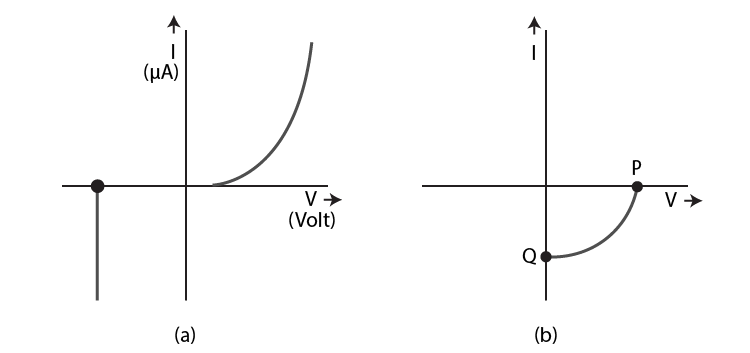
(i) Name the type of a diode whose characteristics are shown in the figure (a) and in the figure (b)

(ii) What does the point P in the figure (a) represent?

(iii) What does the points P and Q in the figure (b) represent?

Show solutionHide solution
Worked solution

i) Figure a) represents the characteristics of Zener diode and figure b) represents the solar cell.

ii) Figure a) point P is the representation of Zener breakdown voltage.

iii) Figure b) point Q is the representation of zero voltage and negative current.

Q14.24Written answer

Three photodiodes D1, D2 and D3 are made of semiconductors having band gaps of 2.5eV, 2eV and 3eV, respectively. Which ones will be able to detect light of wavelength 6000 Ao?

Show solutionHide solution
Worked solution

Wavelength = λ = 6000 Ao = 6000 × 10-10m

Energy of the light photon = E = hc/ λ = 2.06 eV

Q14.25Written answer

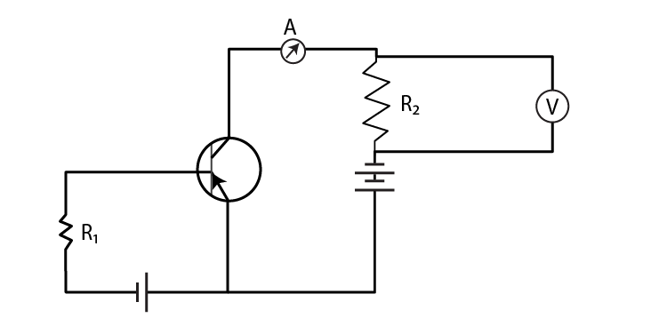
If the resistance R1 is increased, how will the readings of the ammeter and voltmeter change?

Exemplar Solutions Class 12 Physics Chapter 14 - 10

Show solutionHide solution
Worked solution

IbR1 + Vbe = Vbb

Base current = Ib = Vbb – Vbe/R1

Ib is proportional to 1/R1

Therefore, when R1 is increased, Ib decreases.

Q14.26Written answer

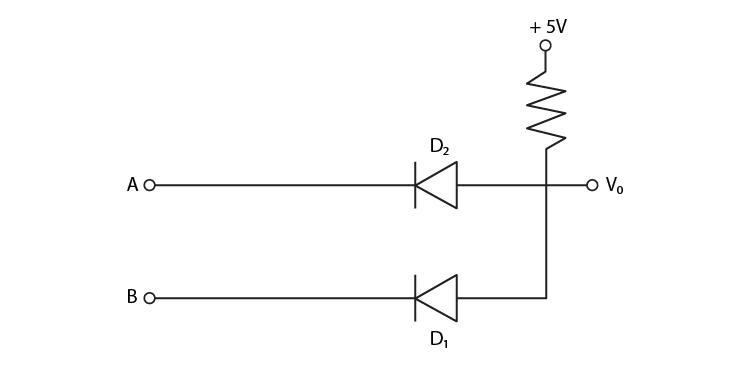
Two car garages have a common gate which needs to open automatically when a car enters either of the garages or cars enter both. Devise a circuit that resembles this situation using diodes for this situation.

Show solutionHide solution
Worked solution

OR gate is used for explaining the situation:

A B Y = A + B
0 0 0
0 1 1
1 0 1
1 1 1
Q14.27Written answer

How would you set up a circuit to obtain NOT gate using a transistor?

Show solutionHide solution
Worked solution

a) It has only one input and only one output

b) Using the Boolean expression

c) Realization of NOT gate

d) Using truth table

Q14.28Written answer

Explain why elemental semiconductor cannot be used to make visible LEDs.

Show solutionHide solution
Worked solution

Elemental semiconductor cannot be used to make visible LEDs because the bandgap of elemental semiconductor is in the infrared region and not in the visible region.

The energy gap for Si is 1.1eV, wavelength is 1129 nm and the energy gap for Ge is 0.7eV, wavelength is 1725 nm.

Q14.29Written answer

Write the truth table for the circuit shown in the figure. Name the gate that the circuit resembles.

Exemplar Solutions Class 12 Physics Chapter 14 - 12

Show solutionHide solution
Worked solution

The given circuit is AND and the truth table is:

A B X = A.B
0 0 0
0 1 0
1 0 0
1 1 1
Q14.30Written answer

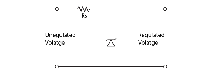
A Zener of power rating 1 W is to be used as a voltage regulator. If Zener has a breakdown of 5V and it has to regulate voltage which fluctuated between 3V and 7V, what should be the value of Rs for safe operation in the figure?

Exemplar Solutions Class 12 Physics Chapter 14 - 13

Show solutionHide solution
Worked solution

Power = 1W

Zener breakdown voltage = 5V

Minimum voltage = 3V

Maximum voltage = 7V

P = VI = 0.2A

Rs = 10 Ohms.

Long Answers
Q14.31Written answer

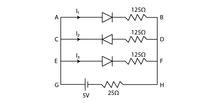
If each diode in the figure has a forward bias resistance of 25Ω and infinite resistance in reverse bias, what will be the values of the current I1, I2, I3 and I4?

Exemplar Solutions Class 12 Physics Chapter 14 - 14

Show solutionHide solution
Worked solution

Forward bias resistance = 25 ohms

Reverse biased resistance = infinity

I3 = 0

Resistance in AB = 150 ohms

Resistance in EF = 150 ohms

AB is parallel to EF

Effective resistance, R’ = 75 ohm

Resistance R of the circuit = R’ = 100 ohms

Current = 0.05 A

I2 = 0.025 A

I4 = 0.025 A

Therefore,

I1 = 0.05 A

I2 = 0.025 A

I3 = 0

I4 = 0.025 A