My Cart
Your Cart 0

    Your cart is empty.

  • Total (Amount) ₹0.00
NCERT · Class 12 · Physics

Chapter 3: Current Electricity

Practice each question, then open the answer or worked solution.

Questions

21 questions
Q3.11Written answer

A storage battery of emf 8.0 V and internal resistance 0.5 Ω is being charged by a 120 V dc supply using a series resistor of 15.5 Ω. What is the terminal voltage of the battery during charging? What is the purpose of having a series resistor in the charging circuit?


Show solutionHide solution
Worked solution

Given:

The EMF of the given storage battery is E = 8.0 V

The Internal resistance of the battery is given by r = 0.5 Ω

The given DC supply voltage is V = 120 V

The resistance of the resistor is R = 15.5 Ω

Effective voltage in the circuit = V 1

R is connected to the storage battery in series.

Hence, it can be written as

V 1 = V – E

V 1 = 120 – 8 = 112 V

Current flowing in the circuit = I, which is given by the relation,

\(\begin{array}{l}I = \frac{ V ^{ 1 }}{ R + r }\end{array} \)


\(\begin{array}{l}I = \frac{ 112 }{ 15.5 + 5 }\end{array} \)


\(\begin{array}{l}I = \frac{ 112 }{ 16 }\end{array} \)


\(\begin{array}{l}I = 7 A\end{array} \)

We know that Voltage across a resistor R given by the product,

I x R = 7 × 15.5 = 108.5 V

We know that,

DC supply voltage = Terminal voltage + voltage drop across R

Terminal voltage of battery = 120 – 108.5 = 11.5 V

A series resistor, when connected to a charging circuit, limits the current drawn from the external source.

The current will become extremely high in its absence. This is extremely dangerous.


Q3.12Written answer

In a potentiometer arrangement, a cell of emf 1.25 V gives a balance point at 35.0 cm length of the wire. If the cell is replaced by another cell and the balance point shifts to 63.0 cm, what is the emf of the
second cell?

Show solutionHide solution
Worked solution

Emf of the cell, E 1 = 1.25 V

The balance point of the potentiometer, l 1 = 35 cm

The cell is replaced by another cell of emf E 2.

The new balance point of the potentiometer, l 2 = 63 cm

The balance condition is given by the relation,

\(\begin{array}{l}\frac{ E _{ 1 } }{ E _{ 2 } } = \frac{ I _{ 1 } }{ I _{ 2 } }\end{array} \)


\(\begin{array}{l}E _{ 2 } = E _{ 1 } \times \frac{ I_{ 2 } }{ I _{ 1 } }\end{array} \)


\(\begin{array}{l}E _{ 2 } = 1.25 \times \frac{ 63 }{ 35 } = 2.25 V\end{array} \)
Q3.13Written answer

The number density of free electrons in a copper conductor estimated in Example 3.1 is 8.5 × 1028 m–3. How long does an electron take to drift from one end of a wire 3.0 m long to its other end? The area of cross-section of the wire is 2.0 × 10⁻⁶ m2 and it is carrying a current of 3.0 A.

Show solutionHide solution
Worked solution

Given that Number density of free electrons in a copper conductor, n =  8.5 x 10 28 m – 3

Let the Length of the copper wire be l

Given , l = 3.0 m

Let the area of the cross-section of the wire be A = 2.0 x 10 – 6 m 2

The value of the current carried by the wire, I = 3.0 A, which is given  by the equation,

I = n A e V d

Where,

e = electric charge = 1.6 x 10 – 19 C

\(\begin{array}{l}V _{ d } = Drift velocity = \frac{ Length of the wire \left ( l \right ) }{ time taken to cover l \left ( t \right )}\end{array} \)


\(\begin{array}{l}I = n A e \frac{ l }{ t }\end{array} \)


\(\begin{array}{l}t = \frac{ n \times A \times e \times l }{ I }\end{array} \)


\(\begin{array}{l}t = \frac{ 3 \times 8.5 \times 10 ^{ 28 } \times 2 \times 10 ^{ – 6 } \times 1.6 \times 10 ^{ – 19 }}{ 3.0 }\end{array} \)


\(\begin{array}{l}t = 2.7 \times 10 ^{ 4 } sec\end{array} \)
Q3.14Written answer

The earth’s surface has a negative surface charge density of 10–9 C m–2. The potential difference of 400 kV between the top of the atmosphere and the surface results (due to the low conductivity of the lower atmosphere) in a current of only 1800 A over the entire globe. If there were no mechanism of sustaining atmospheric electric field, how much time (roughly) would be required to neutralise the earth’s surface? (This never happens in practice because there is a mechanism to replenish electric charges, namely the continual thunderstorms and lightning in different parts of the globe). (Radius of earth = 6.37 × 10⁶ m.)

Show solutionHide solution
Worked solution

Surface charge density of the earth, σ=10−9 cm−2
Potential difference between the top of the atmosphere and the surface, V= 400 kV
Current over the entire globe, I=1800 A
Radius of the earth, r=6.37×10⁶ m
Surface area of the earth, A=4πr2 

= 4 x 3.14 x (6.37×106 )2=5.09×10¹⁴ m2

Charge on the earth’s surface, q=σA= 10−9 x 5.09×1014 

= 5.09×10⁵ C

Time taken to neutralize the earth’s surface, t = q/I

⟹t=5.09×10⁵/1800=283 s

Q3.15Written answer

(a) Six lead-acid type of secondary cells each of emf 2.0 V and internal resistance 0.015 Ω are joined in series to provide a supply to a resistance of 8.5 Ω. What is the current drawn from the supply and its terminal voltage?
(b) A secondary cell after long use has an emf of 1.9 V and a large internal resistance of 380 Ω. What maximum current can be drawn from the cell? Could the cell drive the starting motor of a car?

Show solutionHide solution
Worked solution

(a) Emf of the secondary cells, ε = 2.0 V

Number of secondary cells, n = 6

Total EMF, E= nε= 6 x 2 = 12 V

The internal resistance of the secondary cells, r= 0.015 Ω

Resistance to which the secondary cells are connected, R = 8.5 Ω
Total resistance in circuit Rtotal = nr+ R = 6×0.015+8.5=8.59Ω

Current drawn from the supply, I=E/Rtotal =12/8.59 = 1.4 A
Terminal voltage, V= IR = 1.4×8.5=11.9 V

(b) Emf of the secondary cell, ε = 1.9 V

Internal resistance, r = 380 Ω
Maximum current drawn from the cell,I =ε/r =  1.9/380=0.005A.

The current required to start a motor is 100 Amp. Here, the current produced is 0.005 A, so the starting motor of the car cannot be started with this current.

Q3.16Written answer

Two wires of equal length, one of aluminium and the other of copper have the same resistance. Which of the two wires is lighter? Hence explain why aluminium wires are preferred for overhead power cables. (ρAl = 2.63 × 10⁻⁸ Ω m, ρCu = 1.72 × 10⁻⁸ Ω m, Relative density of Al = 2.7, of Cu = 8.9.)

Show solutionHide solution
Worked solution

Length of aluminium = l1

Resistance of aluminium = R

Resistivity of aluminium, ρAI =ρ1= 2.63×10⁻⁸ Ωm

Relative density of aluminium, d1 =2.7

Area of the cross-section of the aluminium wire =A1

Length of copper = l2

Resistance of copper = R2

Resistivity of copper, ρcu =ρ2=1.72 × 10⁻⁸ Ω m

Relative density of copper, d2 = 8.9

Area of the cross-section of the copper wire =A2

Therefore,

\(\begin{array}{l}R_{1}=\rho _{1}\frac{l_{1}}{A_{1}}\end{array} \)
\(\begin{array}{l}R_{2}=\rho _{2}\frac{l_{2}}{A_{2}}\end{array} \)

It is given that R1 = R2
Therefore,

\(\begin{array}{l}\rho _{1}\frac{l_{1}}{A_{1}}= \rho _{2}\frac{l_{2}}{A_{2}}\end{array} \)

Given l1 = l2

​

\(\begin{array}{l}\frac{\rho _{1}}{A_{1}}= \frac{\rho _{2}}{A_{2}}\end{array} \)
\(\begin{array}{l}\frac{A_{1}}{A_{2}}= \frac{\rho _{1}}{\rho _{2}}\end{array} \)

=  (2.63×10⁻⁸)/(1.72 × 10–8)
​= 1.52

Mass of aluminium, m1 = Volume x density

= A1l1 x d1

Mass of copper = m2 = Volume x density

= A2l2 x d2

m1/m2 =(A1l1 x d1 / A2l2 x d2)
Since l1 = l2

m1/m2 =(A1 d1 / A2d2)

m1/m2 = (1.52) x (2.7/8.9)

= (1.52) x (0.303)

m1/m2 = 0.46

The mass ratio of aluminium to copper is 0.46. Since aluminium is lighter, it is preferred for long suspensions of cables

​Question 3.17:

What conclusion can you draw from the following observations on a resistor made of alloy manganin?

Current A Voltage V Current A  Voltage V
0.2 3.94 3.0 59.2
0.4 7.87 4.0 78.8
0.6 11.8 5.0 98.6
0.8 15.7 6.0 118.5
1.0 19.7 7.0 138.2
2.0 39.4 8.0 158.0

Ohm’s law is valid with high accuracy. This means that the resistivity of the alloy manganin is nearly independent of temperature.

Q3.18Written answer

Answer the following questions:
(a) A steady current flows in a metallic conductor of the non-uniform cross-section. Which of these quantities is constant along the conductor: current, current density, electric field, drift speed?
(b) Is Ohm’s law universally applicable for all conducting elements? If not, give examples of elements that do not obey Ohm’s law.
(c) A low voltage supply from which one needs high currents must have very low internal resistance. Why?
(d) A high tension (HT) supply of, say, 6 kV must have a very large internal resistance. Why?

Show solutionHide solution
Worked solution

(a) Current is given to be steady. Therefore, it is a constant.  The current density, electric field, drift speed depends on the area of the cross-section inversely.
(b) No, examples of non-ohmic elements are vacuum diodes, semiconductor diodes, etc.
(c) Because the maximum current drawn from a source = ε/r.
(d) If the circuit is shorted (accidentally), the current drawn will exceed safety limits if the internal resistance is not large.

Q3.19Written answer

Question 3. 19:

Choose the correct alternative:
(a) Alloys of metals usually have (greater/less) resistivity than that of their constituent metals.
(b) Alloys usually have much (lower/higher) temperature coefficients of resistance than pure metals.
(c) The resistivity of the alloy manganin is nearly independent of/ increases rapidly with increase of temperature.
(d) The resistivity of a typical insulator (e.g., amber) is greater than that of a metal by a factor of the order of (1022/1023).

Show solutionHide solution
Worked solution

(a) greater

(b) lower

(c) nearly independent of

(d) 1022

Q3.20Written answer

(a) Given n resistors each of resistance R, how will you combine them to get the (i) maximum (ii) minimum effective resistance? What is the ratio of the maximum to minimum resistance?
(b) Given the resistances of 1 Ω, 2 Ω, 3 Ω, how will be combine them to get an equivalent resistance of (i) (11/3) Ω (ii) (11/5) Ω, (iii) 6Ω, (iv) (6/11) Ω?
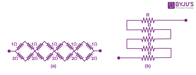
(c) Determine the equivalent resistance of networks shown in figure
NCERT Solutions for Class 12 Physics Chapter 3 Current Electricity Question 20 Solution - image 1

(a) Total number of resistors = n

Resistance of each resistor = R

(i) The maximum effective resistance is got when the resistors are connected in series. The effective resistance R1 = nR

(ii) The minimum effective resistance is got when the resistors are connected in parallel, the effective resistance R2 = R/n

The ratio of maximum resistance to minimum resistance = nR/(R/n) = n2

(b) The resistance given are 1 Ω, 2 Ω, 3 Ω

(i) 11/3 Ω

Consider the following combination

NCERT Solutions for Class 12 Physics Chapter 3 Current Electricity Question 20 Solution - image 2

The resistors of resistance 1 Ω and 2 Ω are parallel. Therefore, effective resistance 

\(\begin{array}{l}\frac{1}{R’} = \left [\frac{1}{1}+\frac{1}{2} \right ]= 3/2\end{array} \)

R’ = 2/3 Ω

These resistors are connected in series with 3 Ω. Therefore the effective resistance R = R’ + 3 = (2/3) +3 = 11/3 Ω

(ii)  11/5 Ω

Consider the following combination

NCERT Solutions for Class 12 Physics Chapter 3 Current Electricity Question 20 Solution - image 3

The resistors of resistance 2 Ω and 3 Ω are parallel. Therefore, effective resistance 

\(\begin{array}{l}\frac{1}{R’} = \left [\frac{1}{2}+\frac{1}{3} \right ]= 5/6\end{array} \)

R’ = 6/5 Ω

These resistors are connected in series with 3 Ω. Therefore the effective resistance R = R’ + 3 = (6/5) +1 = 11/5 Ω

(iii) 6 Ω

When the resistors with resistance 1 Ω, 2 Ω, 3 Ω are connected in series the effective resistance is given by

1 Ω +2 Ω + 3 Ω = 6 Ω

(iv) (6/11) Ω

When the resistors are connected in parallel the effective resistance is 

\(\begin{array}{l}\frac{1}{R’} = \left [\frac{1}{1}+\frac{1}{2} +\frac{1}{3}\right ]= 11/6 \Omega\end{array} \)

R’ = (6/11) Ω

(c) (a) In all the loops, two resistors of resistance 1Ω are connected in series. Therefore, the effective resistance is (1+1) = 2 Ω

Similarly, In all the loops, two resistors of resistance 2Ω are connected in series. Therefore, the effective resistance is (2+2) = 4 Ω

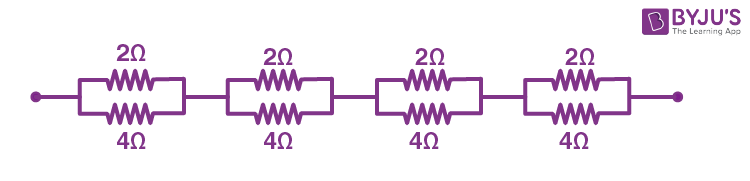
The 2Ω and 4Ω resistors are connected in parallel in all four loops. Therefore, the effective resistance = 

\(\begin{array}{l}\frac{1}{R’} = \left [\frac{1}{2} +\frac{1}{4}\right ]= 3/4 \Omega\end{array} \)

R’ = 4/3 Ω
NCERT Solutions for Class 12 Physics Chapter 3 Current Electricity Question 20 Solution - image 4

NCERT Solutions for Class 12 Physics Chapter 3 Current Electricity Question 20 Solution - image 5

All four resistors are connected in series. Hence the equivalent resistance R each is (4/3) x 4 = 16/3 Ω

(c) (b) The resistors are connected in series. Therefore, the effective resistance is R + R+R+R+R = 5R

Question 3.21:

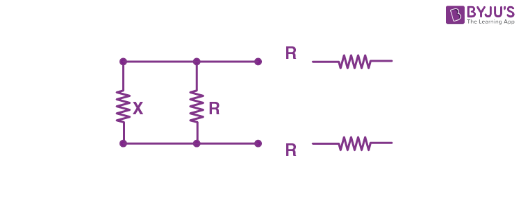
Determine the current drawn from a 12V supply with internal resistance 0.5Ω by the infinite network shown in the figure. Each resistor has 1Ω resistance.
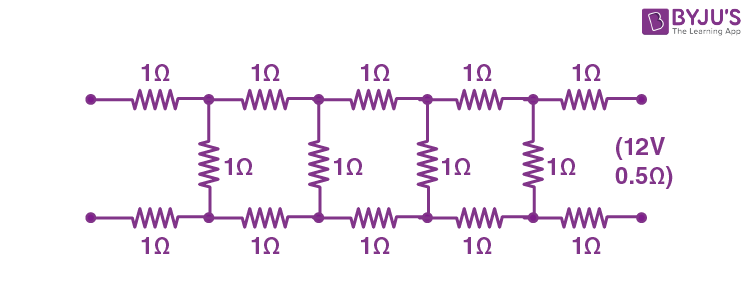
NCERT Solutions for Class 12 Physics Chapter 3 Current Electricity Question 21 Solution - image 1

Show solutionHide solution
Worked solution

Let the effective resistance of the infinite network be X. Since it is an infinite network, adding three resistors of 1 Ω resistance will not change the total resistance, i.e., it will remain X.  The circuit will look like this if three resistors are added.

NCERT Solutions for Class 12 Physics Chapter 3 Current Electricity Question 21 Solution - image 2

The equivalent resistance of this network is R’ = R + (equivalent resistance when X and R are parallel) + R

= R + [XR/(X+R)] + R

R’ = 2R +  [XR/(X+R)]

As said above, since it is an infinite network, adding three resistors of 1 Ω resistance will not change the total resistance.

R’ = X

⇒  2R +  [XR/(X+R)] = X

Since R = 1Ω we get

2 x 1 +  [X x 1/(X+1)] = X

X2 – 2X -2 = 0

\(\begin{array}{l}X = \frac{(-2)\pm \sqrt{(-2)^{2}-4\times 1\times (-2)}}{2}\end{array} \)


\(\begin{array}{l}X = 1\pm \sqrt{3}\end{array} \)

The value of resistance cannot be negative. Therefore, X= 1+√3 = 2.732 Ω

Given E = 12 V ; r = 0.5 Ω

If I is the current drawn by the network, then

I = E/(X+r) = 12/(2.732+ 0.5) = 3.713 A

Q3.22Multiple choice

Question 3. 22:

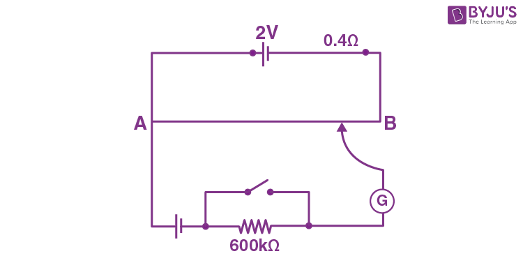
Figure shows a potentiometer with a cell of 2.0 V and internal resistance 0.40 Ω maintaining a potential drop across the resistor wire AB. A standard cell which maintains a constant emf of 1.02 V (for very moderate currents upto a few mA) gives a balance point at 67.3 cm length of the wire. To ensure very low currents drawn from the standard cell, a very high resistance of 600 kΩ is put in series with it, which is shorted close to the balance point. The standard cell is then replaced by a cell of unknown emf ε and the balance point found similarly, turns out to be at 82.3 cm length of the wire.

NCERT Solutions for Class 12 Physics Chapter 3 Current Electricity Question 22 Solution

(e) Would the circuit work well for determining an extremely small emf, say of the order of a few mV (such as the typical emf of a thermo-couple)? If not, how will you modify the circuit?

Show answerHide answer
Correct option: A
Show solutionHide solution
Worked solution

(a) Constant emf of the standard cell, E1 = 1.02 V

The balance point on the wire, l1 = 67.3 cm

The standard cell is then replaced by a cell of unknown emf ε and the balance point changes to l =  82.3 cm

The relation between Emf and the balancing point

(E1/l1) = (ε/l)

ε = (l x E1/l1) = (82.3  x 1.02)/67.3  = 1.247 V

(b) The purpose of using high resistance of 600 kΩ is to reduce current through the galvanometer when the movable contact is far from the balance point.

(c) No.

(d) No. If ε is greater than the emf of the driver cell of the potentiometer, there will be no balance point on the wire AB.

(e) The circuit will not be suitable, because the balance point (for ε of the order of a few mV) will be very close to the end A and the percentage of error in the measurement will be very large. The circuit can be modified by putting a suitable resistor R in series with the wire AB so that the potential drop across AB is only slightly greater than the emf to be measured. Then, the balance point will be at a larger length of the wire and the percentage error will be much smaller.