My Cart
Your Cart 0

    Your cart is empty.

  • Total (Amount) ₹0.00
NCERT · Class 12 · Physics

Chapter 3: Current Electricity

Practice each question, then open the answer or worked solution.

Questions

21 questions
Q3.1Written answer

The storage battery of a car has an emf of 12 V. If the internal resistance of the battery is 0.4 Ω, what is the maximum current that can be drawn from the battery?

Show solutionHide solution
Worked solution

In the given question,

The EMF of the battery is given as E = 12 V

The internal resistance of the battery is given as R = 0.4 Ω

The amount of maximum current drawn from the battery is I

According to Ohm’s law,

E = IR

Rearranging, we get

\(\begin{array}{l}I = \frac{ E }{ R }\end{array} \)

Substituting values in the above equation, we get

\(\begin{array}{l}I = \frac{ 12 }{ 0.4 }\end{array} \)

Therefore, the maximum current drawn from the given battery is 30 A.


Q3.2Written answer

A battery of EMF 10 V and internal resistance 3 Ω is connected to a resistor. If the current in the circuit is 0.5 A, what is the resistance of the resistor? What is the terminal voltage of the battery when the circuit is closed?

Show solutionHide solution
Worked solution

Given:

The EMF of the battery (E = 10 V)

The internal resistance of the battery (R = 3 Ω)

The current in the circuit (I = 0.5 A)

Consider the resistance of the resistor to be R.

The current in the circuit can be found out using Ohm’s Law as,

\(\begin{array}{l}I = \frac{ E }{ R + r }\end{array} \)

Rewriting the above equation, we get

\(\begin{array}{l} R + r = \frac{E}{I}\end{array} \)
\(\begin{array}{l} = \frac{10}{0.5} = 20 Ω\end{array} \)

Therefore,

\(\begin{array}{l}R = 20 – 3 = 17 Ω\end{array} \)

Consider the Terminal voltage of the resistor to be V.

Then, according to Ohm’s law,

V = IR

Substituting values in the equation, we get

V = 0.5 × 17

V = 8.5 V

Therefore, the resistance of the resistor is 17 Ω, and the terminal voltage is 8.5 V.


Q3.3Written answer

a) Three resistors 1 Ω, 2 Ω, and 3 Ω are combined in series. What is the total resistance of the combination?

b) If the combination is connected to a battery of emf 12 V and negligible internal resistance, obtain the potential drop across each resistor.

Show solutionHide solution
Worked solution

a) We know that resistors r 1 = 1 Ω , r 2 = 2 Ω and r 3 = 3 Ω are combined in series.

The total resistance of the above series combination can be calculated by the algebraic sum of individual resistances as follows:

Total resistance = 1 Ω + 2 Ω + 3 Ω = 6 Ω

Thus calculated Total Resistance = 6 Ω

b) Let us consider I to be the current flowing the given circuit

Also,

The emf of the battery is E = 12 V

The total resistance of the circuit ( calculated above ) = R = 6 Ω

Using Ohm’s law, the relation for current can be obtained as

\(\begin{array}{l}I = \frac{ E }{ R }\end{array} \)

Substituting values in the above equation, we get

\(\begin{array}{l}I = \frac{ 12 }{ 6 }\end{array} \)

Therefore, the current calculated is 2 A

Let the Potential drop across 1 Ω resistor = V 1

The value of V 1 can be obtained from Ohm’s law as :

V 1 = 2 x 1 = 2 V

Let the Potential drop across 2 Ω resistor = V 2

The value of V 2 can be obtained from Ohm’s law as:

V 2 = 2 x 2 = 4 V

Let the Potential drop across 3 Ω resistor = V 3

The value of V 3 can be obtained from Ohm’s law as:

V 3 = 2 x 3 = 6 V

Therefore, the potential drops across the given resistors r 1 = 1 Ω , r 2 = 2 Ω and r 3 = 3 Ω are calculated to be

V 1 = 2 x 1 = 2 V

V 2 = 2 x 1 = 4 V

V 3 = 2 x 1 = 6 V


Q3.4Written answer

a) Three resistors 2 Ω, 4 Ω and 5 Ω are combined in parallel. What is the total resistance of the combination?

b) If the combination is connected to a battery of emf 20 V and negligible internal resistance, determine the current through each resistor, and the total current drawn from the battery.

Show solutionHide solution
Worked solution

A ) Resistors r 1 = 2 Ω , r2 = 4 Ω and r 3 = 5 Ω are combined in parallel

Hence the total resistance of the above circuit can be calculated  by the following formula:

\(\begin{array}{l}\frac{ 1 }{ R } = \frac{ 1 }{ R_1 } + \frac{ 1 }{ R_2 } + \frac{ 1 }{ R_3 }\end{array} \)


\(\begin{array}{l}\frac{ 1 }{ R } = \frac{ 1 }{ 2 } + \frac{ 1 }{ 4 } + \frac{ 1 }{ 5 }\end{array} \)


\(\begin{array}{l}\frac{ 1 }{ R } = \frac{ 10 + 5 + 4 }{ 20 }\end{array} \)


\(\begin{array}{l}\frac{ 1 }{ R } = \frac{ 19 }{ 20 }\end{array} \)

Therefore, the total resistance of the parallel combination given above is given by:

\(\begin{array}{l}R = \frac{20}{19}\end{array} \)

B ) Given that emf of the battery, E = 20 V

Let the current flowing through resistor R 1 be I 1

I 1 is given by :

\(\begin{array}{l}I_{ 1 } = \frac{ V }{ R_{ 1 }}\end{array} \)


\(\begin{array}{l}I_{ 1 } = \frac{ 20 }{ 2 }\end{array} \)


\(\begin{array}{l}I_{ 1 } = 10 A\end{array} \)

Let the current flowing through resistor R 2 be I 2

I 2 is given by :

\(\begin{array}{l}I_{ 2 } = \frac{ V }{ R_{ 2 }}\end{array} \)


\(\begin{array}{l}I_{ 2 } = \frac{ 20 }{ 4 }\end{array} \)


\(\begin{array}{l}I_{ 2 } = 5 A\end{array} \)


Let the current flowing through resistor R 3 be I 3

I 3 is given by :

\(\begin{array}{l}I_{ 3 } = \frac{ V }{ R_{ 1 }}\end{array} \)


\(\begin{array}{l}I_{ 3 } = \frac{ 20 }{ 5 }\end{array} \)


\(\begin{array}{l}I_{ 3 } = 4 A\end{array} \)

Therefore, the total current can be found by the following formula :

I = I 1 + I 2 + I 3 = 10 + 5 + 4 = 19 A

therefore the current flowing through each resistor is calculated to be :

\(\begin{array}{l}I_{ 1 } = 10 A\end{array} \)


\(\begin{array}{l}I_{ 2 } = 5 A\end{array} \)


\(\begin{array}{l}I_{ 3 } = 4 A\end{array} \)

Therefore, the total current is I = 19 A

Q3.5Written answer

At room temperature (27.0 °C) the resistance of a heating element is 100 Ω. What is the temperature of the element if the resistance is found to be 117 Ω, given that the temperature coefficient of the material of the resistor is 1.70 × 10⁻⁴ °C–1.

Show solutionHide solution
Worked solution

Given that the room temperature, T = 27 ° C

The heating element has a resistance of R = 100 Ω

Let the increased temperature of the filament be T 1

At T 1, the resistance of the heating element is  R 1 = 117 Ω

Temperature coefficient of the material used for the element is 1.70 x 10– 4 C – 1

α = 1.70 x 10 -4C– 1

α is given by the relation ,

\(\begin{array}{l}\alpha = \frac{ R_{ 1 } – R }{ R \left ( T _{ 1 } – T \right )}\end{array} \)


\(\begin{array}{l}T _{ 1 } – T = \frac{ R _{ 1 } – R }{ R \alpha}\end{array} \)


\(\begin{array}{l}T _{ 1 } – 27 = \frac{ 117 – 100 }{ 100 ( 1.7 × 10^{-4}) }\end{array} \)


\(\begin{array}{l}T _{ 1 } – 27 = 1000\end{array} \)

T 1 = 1027 ° C

Therefore, the resistance of the element is 117 Ω at T 1 = 1027 ° C


Q3.6Written answer

A negligibly small current is passed through a wire of length 15 m and uniform cross-section 6.0 × 10⁻⁷ m2, and its resistance is measured to be 5.0 Ω. What is the resistivity of the material at the temperature of the experiment?

Show solutionHide solution
Worked solution

Given that the length of the wire, L = 15 m

The area of cross-section is given as , a = 6.0 x 10 – 7 m 2

Let the resistance of the material of the wire be, R, i.e., R = 5.0 Ω

The resistivity of the material is given as ρ

\(\begin{array}{l}R = \rho \frac{ L }{ A }\end{array} \)


\(\begin{array}{l}\rho = \frac{ R \times A }{ L } = \frac{ 5 \times 6 \times 10 ^{ – 7 }}{ 15 } = 2 \times 10 ^{ – 7 }\end{array} \)

Therefore, the resistivity of the material is calculated to be

\(\begin{array}{l}2 \times 10 ^{ – 7 }\end{array} \)


Q3.7Written answer

A silver wire has a resistance of 2.1 Ω at 27.5 °C, and a resistance of 2.7 Ω at 100 °C. Determine the temperature coefficient of resistivity of silver.

Show solutionHide solution
Worked solution

Given that temperature T 1 = 27.5 ° C

Resistance R 1 at temperature T 1 is given as :

R 1 =  2.1 Ω ( at T 1 )

Given that temperature T 2 = 100 ° C

Resistance R 2 at temperature T 2 is given as :

R 2 =  2.7 Ω ( at T 2 )

Temperature coefficient of resistivity of silver = α

\(\begin{array}{l}\alpha = \frac{ R _{ 2 } – R _{ 1 }}{ R _{ 1 } \left ( T _{ 2 } – T _{ 1 }\right )}\end{array} \)


\(\begin{array}{l}\alpha = \frac{ 2.7 – 2.1 }{ 2.1 \left ( 100 – 27.5 \right )} = 0.0039 ^{\circ} C ^{ – 1 }\end{array} \)

Therefore, the temperature coefficient of resistivity of silver is

\(\begin{array}{l}0.0039 ^{\circ} C ^{ – 1 }\end{array} \)


Q3.8Written answer

A heating element using nichrome connected to a 230 V supply draws an initial current of 3.2 A which settles after a few seconds to a steady value of 2.8 A. What is the steady temperature of the heating element if the room temperature is 27.0 °C? Temperature coefficient of resistance of nichrome averaged over the temperature range involved is 1.70 × 10⁻⁴ °C–1.

Show solutionHide solution
Worked solution

In the given problem,

The supply voltage, V = 230 V

The initial current drawn, I 1 = 3.2 A

Consider the initial resistance to be R 1, which can be found by the following relation:

\(\begin{array}{l}R _{ 1 } = \frac{ V }{ I }\end{array} \)

Substituting the values, we get

\(\begin{array}{l}R _{ 1 } = \frac{ 230 }{ 3.2 }\end{array} \)

Value of current at steady state, I 2 = 2.8 A

Value of resistance at steady state = R 2

R 2 can be calculated by the following equation:

\(\begin{array}{l}R _{ 2 } = \frac{ 230 }{ 2.8 } = 82.14 Ω\end{array} \)

The temperature coefficient of nichrome averaged over the temperature range involved is 1.70 x 10 – 4 ° C – 1

Value of initial temperature of nichrome , T 1 = 27.0 ° C

Value of steady-state temperature reached by nichrome = T 2

This temperature T 2 can be obtained by the following formula:

\(\begin{array}{l}\alpha = \frac{ R _{ 2 } – R _{ 1 }}{ R _{ 1 } \left ( T _{ 2 } – T _{ 1 }\right )}\end{array} \)


\(\begin{array}{l}T _{ 2 } – 27 = \frac{ 82.14 – 71.87 }{ 71.87 \times ( 1.7 \times 10^{-4}) }\end{array} \)


\(\begin{array}{l}T_{ 2 } – 27 = 840.5\end{array} \)

T 2 = 840.5 + 27 = 867.5 ° C

Hence, the steady temperature of the heating element is 867.5 ° C


Q3.9Written answer

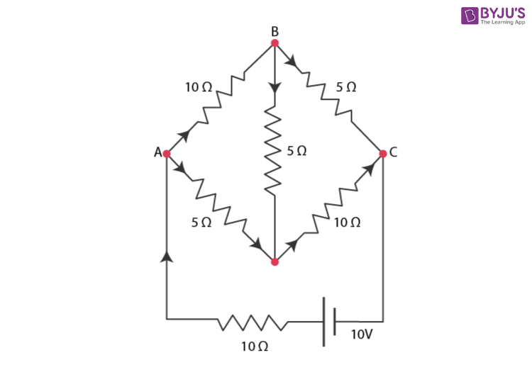
Determine the current in each branch of the network shown in the figure:

NCERT-Solutions-for-Class-12-Physics-Chapter-3-Current-Electricity Question 9

Show solutionHide solution
Worked solution

The current flowing through various branches of the network is shown in the figure given below:

NCERT Solutions for Class 12 Physics Chapter 3 Current Electricity Question 9 Solution

Let I 1 be the current flowing through the outer circuit

Let I 2 be the current flowing through AB branch

Let I 3 be the current flowing through AD branch

Let I 2 – I 4 be the current flowing through branch BC

Let I 3 + I 4 be the current flowing through branch DC

Let us take closed-circuit ABDA into consideration, we know that potential is zero.

i.e ,  10 I 2 + 5 I 4 – 5 I 3 = 0

2 I 2 +  I 4 –  I 3 = 0

I 3 = 2 I 2 +  I 4                                                                                               . . . . . . . . . . . . . . . . . . . . . . eq ( 1 )


Let us take closed circuit BCDB into consideration, we know that potential is zero.

i.e.,  5 ( I 2 – I 4 ) – 10 ( I 3 + I 4 ) – 5 I 4 = 0

5 I 2 – 5 I 4 – 10 I 3 – 10 I 4 –  5 I 4 = 0

5 I 2 – 10 I 3 –  20 I 4 = 0

I 2 = 2 I 3 – 4 I 4                                                                                          . . . . . . . . . . . . . . . . . . . . . . eq ( 2 )


Let us take closed-circuit ABCFEA into consideration, we know that potential is zero.

i.e ,  – 10 + 10 ( I 1 ) + 10 ( I 2 ) + 5 ( I 2 –  I 4 ) = 0

10 = 15 I 2 + 10 I 1 – 5 I 4

3 I 2 + 2 I 2 – I 4 = 2                                                                                    . . . . . . . . . . . . . . . . . . . . . . eq ( 3 )

From equation ( 1 )  and ( 2 ), we have :

I 3 = 2 ( 2 I 3 + 4 I 4 ) + I 4

I 3 = 4 I 3 + 8 I 4 + I 4

– 3 I 3 = 9 I 4

– 3 I 4 = + I 3                                                                                            . . . . . . . . . . . . . . . . . . . . . . eq ( 4 )

Putting equation  ( 4 ) in equation ( 1 ) , we have  :

I 3 = 2 I 2 + I 4

– 4 I 4 = 2 I 2

I 2 = – 2 I 4                                                                                                . . . . . . . . . . . . . . . . . . . . . . eq ( 5 )

From the above equation , we infer that :

I 1 = I 3 + I 2                                                                                                   . . . . . . . . . . . . . . . . . . . . . . eq ( 6 )

Putting equation ( 4 ) in equation ( 1 ), we obtain

3 I 2 + 2 ( I 3 + I 2 ) – I 4 = 2

5 I 2 + 2 I 3 – I 4 = 2                                                                                  . . . . . . . . . . . . . . . . . . . . . . eq ( 7 )

Putting equations ( 4 ) and ( 5 ) in equation ( 7 ), we obtain

5 ( – 2 I 4 ) + 2 ( – 3 I 4 ) – I 4 = 2

– 10 I 4 –  6 I 4 – I 4 = 2

17 I 4 = – 2

\(\begin{array}{l}I _{ 4 } = \frac{ – 2 }{ 17 } A\end{array} \)

Equation ( 4 ) reduces to

I 3 = – 3 ( I 4 )

\(\begin{array}{l}I_{ 3 } = – 3 \left ( \frac{ – 2 }{ 17 } \right ) = \frac{ 6 }{ 17 } A\end{array} \)

I 2 = – 2 ( I 4 )

\(\begin{array}{l}I_{ 2 } = – 2 \left ( \frac{ – 2 }{ 17 } \right ) = \frac{ 4 }{ 17 } A\end{array} \)


\(\begin{array}{l}I _{ 2 } – I _{ 4 } = \frac{ 4 }{ 17 } – \frac{ – 2 }{ 17 } = \frac{ 6 }{ 17 } A\end{array} \)


\(\begin{array}{l}I _{ 3 } + I _{ 4 } = \frac{ 6 }{ 17 } – \frac{ – 2 }{ 17 } = \frac{ 4 }{ 17 } A\end{array} \)


\(\begin{array}{l}I _{ 1 } = I _{ 3 } + I _{ 2 }\end{array} \)


\(\begin{array}{l}I _{ 1 } = \frac{ 6 }{ 17 } + \frac{ 4 }{ 17 } = \frac{ 10 }{ 17 } A\end{array} \)

Therefore, current in each branch is given as :

In branch

\(\begin{array}{l}AB = \frac{ 4 }{ 17 } A\end{array} \)

In branch

\(\begin{array}{l}BC = \frac{ 6 }{ 17 } A\end{array} \)

In branch

\(\begin{array}{l}CD = \frac{ – 4 }{ 17 } A\end{array} \)

In branch

\(\begin{array}{l}AD = \frac{ 6 }{ 17 } A\end{array} \)

In branch

\(\begin{array}{l}BD = \frac{ – 2 }{ 17 } A\end{array} \)

Total current 

\(\begin{array}{l}= \frac{ 4 }{ 17 } + \frac{ 6 }{ 17 } + \frac{ – 4 }{ 17 } + \frac{ 6 }{ 17 } + \frac{ – 2 }{ 17 } = \frac{ 10 }{ 17 } A\end{array} \)
 

Q3.10Written answer

Question 3. 10:

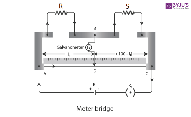
A ) In a meter bridge given below, the balance point is found to be at 39.5 cm from the end A, when the resistor S is of 12.5 Ω. Determine the resistance of R. Why are the connections between resistors in a Wheatstone or meter bridge made of thick copper strips?

B ) Determine the balance point of the bridge above if R and S are interchanged.

C ) What happens if the galvanometer and cell are interchanged at the balance point of the bridge? Would the galvanometer show any current?

NCERT Solutions for Class 12 Physics Chapter 3 Current Electricity Question 10 Solution

Show solutionHide solution
Worked solution

( a ) Let L 1 be the balance point from end A,

Given that , L 1 = 39.5 cm

Given that resistance of the resistor S = 12.5 Ω

We know that condition for the balance is given by the equation:

\(\begin{array}{l}\frac{ R }{ S } = \frac{ 100 – L _{ 1 } }{ L _{ 1 } }\end{array} \)


\(\begin{array}{l}R = \frac{ 100 – 39.5 }{ 39.5 } \times 12.5 = 8.2 \Omega\end{array} \)

Thus calculated the resistance of the resistor R, R = 

\(\begin{array}{l}8.2 \Omega\end{array} \)

(b) If R and S are interchanged, then the lengths will also be interchanged.

Hence, the length modifies to

l = 100 – 39.5 = 60.5 cm.

(c) If the galvanometer and the cell are interchanged, the position of the balance point remains unchanged. Therefore, the galvanometer will show no current.