My Cart
Your Cart 0

    Your cart is empty.

  • Total (Amount) ₹0.00
Previous year question hub

Op-amp Circuits - Analog Circuits - Electronics & Communication Engineering Previous Year Questions

Practice Op-amp Circuits - Analog Circuits - Electronics & Communication Engineering previous year questions organised from real papers, with year-wise coverage and clear topic navigation.

23Papers
16Years
68Questions
1Topics

Op-amp Circuits question pattern

Every graph below is calculated only from this selection.

Questions by year

Year-wise coverage for Op-amp Circuits. Each bar uses a separate theme-derived color.

Difficulty distribution

How the classified questions are distributed by difficulty.

Medium 58 85.3%
Easy 7 10.3%
Hard 3 4.4%
Question type distribution

MCQ, numerical, multiple-select and other formats found in these papers.

MCQ 46 67.6%
Numerical Answer Type (NAT) 19 27.9%
MSQ 2 2.9%
Fill in the blanks 1 1.5%

Subject weightage

Top subjects by unique question coverage.

Electronics & Communication Engineering
68 Qs

Most asked topics

Top topics across the included previous year papers.

Analog Circuits
68 Qs

Subtopic coverage

Top subtopics inside this exact selection.

Op-amp Circuits
68 Qs

Paper coverage

Question coverage for the most populated papers. Every active PYP paper remains listed below.

Electronics and Communication Engineering (EC) 2026
5 Qs
Electronics & Communication Engineering (EC) 2025
3 Qs
Electronics & Communication Engineering (EC) 2024
3 Qs
Electronics & Communication Engineering (EC) 2023
2 Qs
Electronics & Communication Engineering (EC) 2022
5 Qs
Electronics & Communication Engineering (EC) 2021
4 Qs
Electronics & Communication Engineering (EC) 2020
6 Qs
Electronics & Communication Engineering (EC) 2018
3 Qs
Electronics & Communication Engineering (EC) 2017
1 Qs
Electronics & Communication Engineering (EC) 2016 [Session 1]
5 Qs
Electronics & Communication Engineering (EC) 2016 [Session 2]
2 Qs
Electronics & Communication Engineering (EC) 2016 [Session 3]
2 Qs
Electronics & Communication Engineering (EC) 2014 [Session 3]
2 Qs
Electronics & Communication Engineering (EC) 2014 [Session 4]
2 Qs
Electronics & Communication Engineering (EC) 2014 [Session 1]
1 Qs
Electronics & Communication Engineering (EC) 2013 [Session 2]
4 Qs
Electronics & Communication Engineering (EC) 2013 [Session 3]
3 Qs
Electronics & Communication Engineering (EC) 2013 [Session 1]
2 Qs
Electronics & Communication Engineering (EC) 2013 [Session 4]
2 Qs
Electronics & Communication Engineering (EC) 2012
1 Qs
Electronics & Communication Engineering (EC) 2011
2 Qs
Electronics & Communication Engineering (EC) 2010
3 Qs
Electronics & Communication Engineering (EC) 2008
5 Qs

Included previous year papers

Newest papers appear first. Sort by year, question coverage or name.

PaperYear / sessionQuestions in this viewOpen
Electronics and Communication Engineering (EC) 202620265View paper
Electronics & Communication Engineering (EC) 202520253View paper
Electronics & Communication Engineering (EC) 202420243View paper
Electronics & Communication Engineering (EC) 202320232View paper
Electronics & Communication Engineering (EC) 202220225View paper
Electronics & Communication Engineering (EC) 202120214View paper
Electronics & Communication Engineering (EC) 202020206View paper
Electronics & Communication Engineering (EC) 201820183View paper
Electronics & Communication Engineering (EC) 201720171View paper
Electronics & Communication Engineering (EC) 2016 [Session 1]20165View paper
Electronics & Communication Engineering (EC) 2016 [Session 2]20162View paper
Electronics & Communication Engineering (EC) 2016 [Session 3]20162View paper
Electronics & Communication Engineering (EC) 2014 [Session 1]20141View paper
Electronics & Communication Engineering (EC) 2014 [Session 3]20142View paper
Electronics & Communication Engineering (EC) 2014 [Session 4]20142View paper
Electronics & Communication Engineering (EC) 2013 [Session 1]20132View paper
Electronics & Communication Engineering (EC) 2013 [Session 2]20134View paper
Electronics & Communication Engineering (EC) 2013 [Session 3]20133View paper
Electronics & Communication Engineering (EC) 2013 [Session 4]20132View paper
Electronics & Communication Engineering (EC) 201220121View paper
Electronics & Communication Engineering (EC) 201120112View paper
Electronics & Communication Engineering (EC) 201020103View paper
Electronics & Communication Engineering (EC) 200820085View paper

All Op-amp Circuits previous year questions

Practice every matching question in batches of 20, with every available option.

1
2008 · Electronics & Communication Engineering · Analog Circuits · Op-amp Circuits
Electronics & Communication Engineering (EC) 2008
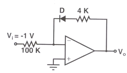
Consider the following circuit using an ideal OPAMP. The I-V characteristics of the diode is described by the relation $I = I_0 \left( e^{\frac{V}{V_T}} - 1 \right)$ where $V_T = 25$ mV, $I_0 = 1$ μA and $V$ is the voltage across the diode (taken as positive for forward bias). For an input voltage $V_I = -1$ V, the output voltage $V_o$ is

Question diagram

Open complete paper
2
2008 · Electronics & Communication Engineering · Analog Circuits · Op-amp Circuits
Electronics & Communication Engineering (EC) 2008

The OPAMP circuit shown above represents a

Question diagram

Open complete paper
3
2008 · Electronics & Communication Engineering · Analog Circuits · Op-amp Circuits
Electronics & Communication Engineering (EC) 2008
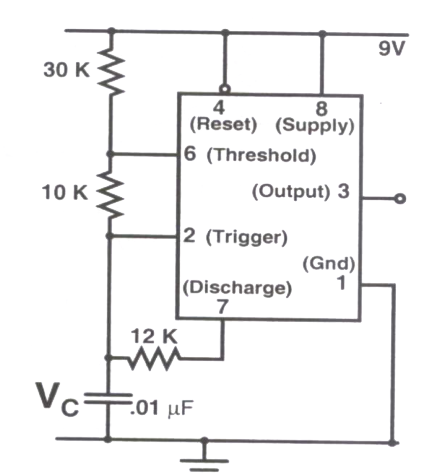
An astable multivibrator circuit using IC 555 timer is shown below. Assume that the circuit is oscillating steadily. The voltage $V_C$ across the capacitor varies between

Question diagram

Open complete paper
4
2008 · Electronics & Communication Engineering · Analog Circuits · Op-amp Circuits
Electronics & Communication Engineering (EC) 2008
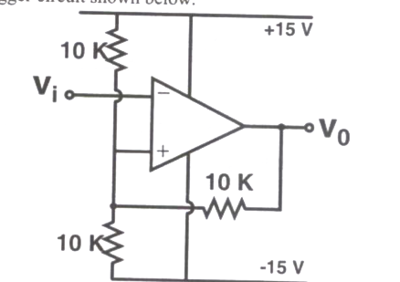
Consider the Schmidt trigger circuit shown below. A triangular wave which goes from -12 V to 12 V is applied to the inverting input of the OPAMP. Assume that the output of the OPAMP swings from +15 V to -15 V. The voltage at the non-inverting input switches between

Question diagram

Open complete paper
5
2008 · Electronics & Communication Engineering · Analog Circuits · Op-amp Circuits
Electronics & Communication Engineering (EC) 2008
The magnitude of the error between V_DAC and V_in at steady state in volts is
Open complete paper
6
2010 · Electronics & Communication Engineering · Analog Circuits · Op-amp Circuits
Electronics & Communication Engineering (EC) 2010

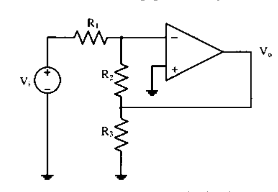
Assuming the OP-AMP to be ideal, the voltage gain of the amplifier shown below is

Question diagram

Open complete paper
7
2010 · Electronics & Communication Engineering · Analog Circuits · Op-amp Circuits
Electronics & Communication Engineering (EC) 2010

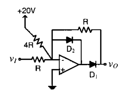
The transfer characteristic for the precision rectifier circuit shown below is (assume ideal OP-AMP and practical diodes)

Question diagram

Open complete paper
8
2010 · Electronics & Communication Engineering · Analog Circuits · Op-amp Circuits
Electronics & Communication Engineering (EC) 2010
The resistance seen by the source vs is
Open complete paper
9
2011 · Electronics & Communication Engineering · Analog Circuits · Op-amp Circuits
Electronics & Communication Engineering (EC) 2011

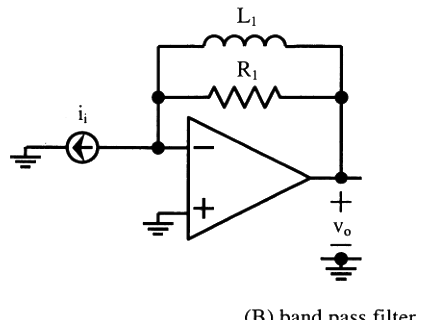
The circuit below implements a filter between the input current \(i_i\) and the output voltage \(v_o\). Assume that the opamp is ideal. The filter implemented is a

Question diagram

Open complete paper
10
2011 · Electronics & Communication Engineering · Analog Circuits · Op-amp Circuits
Electronics & Communication Engineering (EC) 2011
The circuit shown below is driven by a sinusoidal input \(v_i = V_p \cos(t/RC)\). The steady state output \(v_o\) is
Open complete paper
11
2012 · Electronics & Communication Engineering · Analog Circuits · Op-amp Circuits
Electronics & Communication Engineering (EC) 2012

The circuit shown is a

Question diagram

Open complete paper
12
2013 · Electronics & Communication Engineering · Analog Circuits · Op-amp Circuits
Electronics & Communication Engineering (EC) 2013 [Session 1]
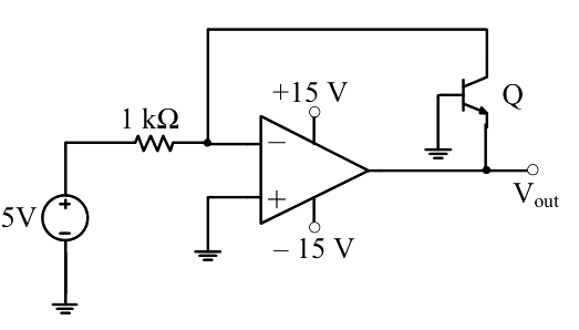
In the circuit shown below what is the output voltage (\( V_{out} \)) if a silicon transistor Q and an ideal op-amp are used?

Question diagram

Open complete paper
13
2013 · Electronics & Communication Engineering · Analog Circuits · Op-amp Circuits
Electronics & Communication Engineering (EC) 2013 [Session 1]
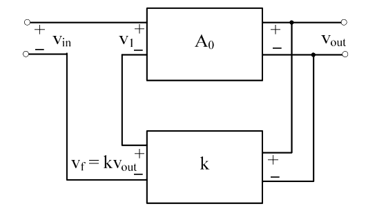
In a voltage-voltage feedback as shown below, which one of the following statements is TRUE if the gain \( k \) is increased?

Question diagram

Open complete paper
14
2013 · Electronics & Communication Engineering · Analog Circuits · Op-amp Circuits
Electronics & Communication Engineering (EC) 2013 [Session 2]
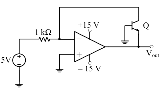
In the circuit shown below what is the output voltage ($V_{out}$) if a silicon transistor Q and an ideal op-amp are used?

Question diagram

Open complete paper
15
2013 · Electronics & Communication Engineering · Analog Circuits · Op-amp Circuits
Electronics & Communication Engineering (EC) 2013 [Session 2]
In the circuit shown below the op-amps are ideal. Then \(V_{out}\) in Volts is
Open complete paper
16
2013 · Electronics & Communication Engineering · Analog Circuits · Op-amp Circuits
Electronics & Communication Engineering (EC) 2013 [Session 2]
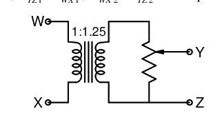
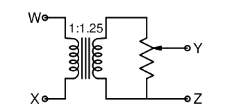
The following arrangement consists of an ideal transformer and an attenuator which attenuates by a factor of 0.8. An ac voltage \(V_{WX1} = 100V\) is applied across WX to get an open circuit voltage \(V_{YZ1}\) across YZ. Next, an ac voltage \(V_{YZ2} = 100V\) is applied across YZ to get an open circuit voltage \(V_{WX2}\) across WX. Then, \(V_{YZ1} / V_{WX1} \), \(V_{WX2} / V_{YZ2}\) are respectively,

Question diagram

Open complete paper
17
2013 · Electronics & Communication Engineering · Analog Circuits · Op-amp Circuits
Electronics & Communication Engineering (EC) 2013 [Session 3]
In the circuit shown below what is the output voltage (Vout) if a silicon transistor Q and an ideal op-amp are used?
Open complete paper
18
2013 · Electronics & Communication Engineering · Analog Circuits · Op-amp Circuits
Electronics & Communication Engineering (EC) 2013 [Session 3]
The following arrangement consists of an ideal transformer and an attenuator which attenuates by a factor of 0.8. An ac voltage \(V_{WX1}=100V\) is applied across WX to get an open circuit voltage \(V_{YZ1}\) across YZ. Next, an ac voltage \(V_{YZ2}=100V\) is applied across YZ to get an open circuit voltage \(V_{WX2}\) across WX. Then, \(V_{YZ1}/V_{WX1}\), \(V_{WX2}/V_{YZ2}\) are respectively,

Question diagram

Open complete paper
19
2013 · Electronics & Communication Engineering · Analog Circuits · Op-amp Circuits
Electronics & Communication Engineering (EC) 2013 [Session 3]
In the circuit shown below the op-amps are ideal. Then Vout in Volts is

Question diagram

Open complete paper
20
2013 · Electronics & Communication Engineering · Analog Circuits · Op-amp Circuits
Electronics & Communication Engineering (EC) 2013 [Session 4]
In the circuit shown below what is the output voltage (\(V_{out}\)) if a silicon transistor Q and an ideal op-amp are used?

Question diagram

Open complete paper

Showing 20 of 66 questions