My Cart
Your Cart 0

    Your cart is empty.

  • Total (Amount) ₹0.00
Previous year question hub

Time and frequency domain analysis of linear circuits - Networks, Signals and Systems - Electronics & Communication Engineering Previous Year Questions

Practice Time and frequency domain analysis of linear circuits - Networks, Signals and Systems - Electronics & Communication Engineering previous year questions organised from real papers, with year-wise coverage and clear topic navigation.

29Papers
19Years
118Questions
1Topics

Time and frequency domain analysis of linear circuits question pattern

Every graph below is calculated only from this selection.

Questions by year

Compare question counts across years.

Difficulty distribution

How the classified questions are distributed by difficulty.

Medium 82 69.5%
Easy 31 26.3%
Hard 5 4.2%

Question type distribution

MCQ, numerical, multiple-select and other formats found in these papers.

MCQ 84 71.2%
Numerical Answer Type (NAT) 22 18.6%
MSQ 6 5.1%
Fill in the blanks 6 5.1%

Subject weightage

Top subjects by unique question coverage.

Electronics & Communication Engineering
118 Qs

Most asked topics

Top topics across the included previous year papers.

Networks, Signals and Systems
118 Qs

Subtopic coverage

Top subtopics inside this exact selection.

Time and frequency domain analysis of linear circuits
118 Qs

Paper coverage

Question coverage for the most populated papers. Every active PYP paper remains listed below.

Electronics and Communication Engineering (EC) 2026
4 Qs
Electronics & Communication Engineering (EC) 2025
2 Qs
Electronics & Communication Engineering (EC) 2024
6 Qs
Electronics & Communication Engineering (EC) 2023
8 Qs
Electronics & Communication Engineering (EC) 2022
3 Qs
Electronics & Communication Engineering (EC) 2021
5 Qs
Electronics & Communication Engineering (EC) 2020
2 Qs
Electronics & Communication Engineering (EC) 2019
4 Qs
Electronics & Communication Engineering (EC) 2018
5 Qs
Electronics & Communication Engineering (EC) 2017 [Session 1]
6 Qs
Electronics & Communication Engineering (EC) 2017 [Session 2]
4 Qs
Electronics & Communication Engineering (EC) 2017
3 Qs
Electronics & Communication Engineering (EC) 2016 [Session 2]
4 Qs
Electronics & Communication Engineering (EC) 2016 [Session 1]
3 Qs
Electronics & Communication Engineering (EC) 2016 [Session 3]
2 Qs
Electronics & Communication Engineering (EC) 2014 [Session 4]
4 Qs
Electronics & Communication Engineering (EC) 2014 [Session 1]
2 Qs
Electronics & Communication Engineering (EC) 2014 [Session 2]
2 Qs
Electronics & Communication Engineering (EC) 2014 [Session 3]
1 Qs
Electronics & Communication Engineering (EC) 2013 [Session 3]
5 Qs
Electronics & Communication Engineering (EC) 2013 [Session 2]
4 Qs
Electronics & Communication Engineering (EC) 2013 [Session 4]
2 Qs
Electronics & Communication Engineering (EC) 2013 [Session 1]
1 Qs
Electronics & Communication Engineering (EC) 2012
4 Qs
Electronics & Communication Engineering (EC) 2011
5 Qs
Electronics & Communication Engineering (EC) 2010
9 Qs
Electronics & Communication Engineering (EC) 2009
6 Qs
Electronics & Communication Engineering (EC) 2008
7 Qs
Electronics & Communication Engineering (EC) 2007
5 Qs

Included previous year papers

Newest papers appear first. Search these papers or sort by year and name.

Paper nameYearPDFAttempt
Electronics and Communication Engineering (EC) 20262026
4 questions in this view
2026
Electronics & Communication Engineering (EC) 20252025
2 questions in this view
2025
Electronics & Communication Engineering (EC) 20242024
6 questions in this view
2024
Electronics & Communication Engineering (EC) 20232023
8 questions in this view
2023
Electronics & Communication Engineering (EC) 20222022
3 questions in this view
2022
Electronics & Communication Engineering (EC) 20212021
5 questions in this view
2021
Electronics & Communication Engineering (EC) 20202020
2 questions in this view
2020
Electronics & Communication Engineering (EC) 20192019
4 questions in this view
2019
Electronics & Communication Engineering (EC) 20182018
5 questions in this view
2018
Electronics & Communication Engineering (EC) 20172017
3 questions in this view
2017
Electronics & Communication Engineering (EC) 2017 [Session 1]2017
6 questions in this view
2017
Electronics & Communication Engineering (EC) 2017 [Session 2]2017
4 questions in this view
2017
Electronics & Communication Engineering (EC) 2016 [Session 1]2016
3 questions in this view
2016
Electronics & Communication Engineering (EC) 2016 [Session 2]2016
4 questions in this view
2016
Electronics & Communication Engineering (EC) 2016 [Session 3]2016
2 questions in this view
2016
Electronics & Communication Engineering (EC) 2014 [Session 1]2014
2 questions in this view
2014
Electronics & Communication Engineering (EC) 2014 [Session 2]2014
2 questions in this view
2014
Electronics & Communication Engineering (EC) 2014 [Session 3]2014
1 questions in this view
2014
Electronics & Communication Engineering (EC) 2014 [Session 4]2014
4 questions in this view
2014
Electronics & Communication Engineering (EC) 2013 [Session 1]2013
1 questions in this view
2013
Electronics & Communication Engineering (EC) 2013 [Session 2]2013
4 questions in this view
2013
Electronics & Communication Engineering (EC) 2013 [Session 3]2013
5 questions in this view
2013
Electronics & Communication Engineering (EC) 2013 [Session 4]2013
2 questions in this view
2013
Electronics & Communication Engineering (EC) 20122012
4 questions in this view
2012
Electronics & Communication Engineering (EC) 20112011
5 questions in this view
2011
Electronics & Communication Engineering (EC) 20102010
9 questions in this view
2010
Electronics & Communication Engineering (EC) 20092009
6 questions in this view
2009
Electronics & Communication Engineering (EC) 20082008
7 questions in this view
2008
Electronics & Communication Engineering (EC) 20072007
5 questions in this view
2007

All Time and frequency domain analysis of linear circuits previous year questions

Practice every matching question in batches of 20, with every available option.

1
2007 · Electronics & Communication Engineering · Networks, Signals and Systems · Time and frequency domain analysis of linear circuits
Electronics & Communication Engineering (EC) 2007
The RC circuit shown in the figure is

Question diagram

Open complete paper
2
2007 · Electronics & Communication Engineering · Networks, Signals and Systems · Time and frequency domain analysis of linear circuits
Electronics & Communication Engineering (EC) 2007
If the Laplace transform of a signal \(y(t)\) is \(Y(s) = \frac{1}{s(s-1)}\), then its final value is
Open complete paper
3
2007 · Electronics & Communication Engineering · Networks, Signals and Systems · Time and frequency domain analysis of linear circuits
Electronics & Communication Engineering (EC) 2007
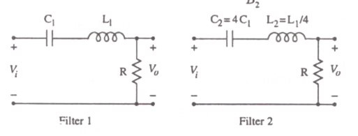
Two series resonant filters are as shown in the figure. Let the 3-dB bandwidth of Filter 1 be B₁ and that of Filter 2 be B₂. The value of B₁/B₂ is

Question diagram

Open complete paper
4
2007 · Electronics & Communication Engineering · Networks, Signals and Systems · Time and frequency domain analysis of linear circuits
Electronics & Communication Engineering (EC) 2007
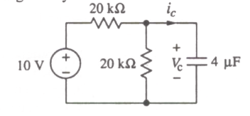
In the circuit shown, V_C is 0 volts at t = 0 sec. For t > 0, the capacitor current i_C(t), where t is in seconds, is given by

Question diagram

Open complete paper
5
2007 · Electronics & Communication Engineering · Networks, Signals and Systems · Time and frequency domain analysis of linear circuits
Electronics & Communication Engineering (EC) 2007
The frequency response of a linear, time-invariant system is given by \(H(f) = \frac{5}{1 + j10\pi f}\). The step response of the system is
Open complete paper
6
2008 · Electronics & Communication Engineering · Networks, Signals and Systems · Time and frequency domain analysis of linear circuits
Electronics & Communication Engineering (EC) 2008

The pole-zero plot given below corresponds to a

Question diagram

Open complete paper
7
2008 · Electronics & Communication Engineering · Networks, Signals and Systems · Time and frequency domain analysis of linear circuits
Electronics & Communication Engineering (EC) 2008
The circuit shown in the figure is used to charge the capacitor C alternately from two current sources as indicated. The switches S1 and S2 are mechanically coupled and connected as follows:

For \(2nT \le t < (2n+1)T\), (n = 0,1,2,···), S1 to P1 and S2 to P2.
For \((2n+1)T \le t < (2n+2)T\), (n = 0,1,2,···), S1 to Q1 and S2 to Q2.

Assume that the capacitor has zero initial charge. Given that \(u(t)\) is a unit step function, the voltage \(V_c(t)\) across the capacitor is given by
Open complete paper
8
2008 · Electronics & Communication Engineering · Networks, Signals and Systems · Time and frequency domain analysis of linear circuits
Electronics & Communication Engineering (EC) 2008
A linear, time-invariant, causal continuous time system has a rational transfer function with simple poles at \(s = -2\) and \(s = -4\), and one simple zero at \(s = -1\). A unit step \(u(t)\) is applied at the input of the system. At steady state, the output has constant value of 1. The impulse response of this system is
Open complete paper
9
2008 · Electronics & Communication Engineering · Networks, Signals and Systems · Time and frequency domain analysis of linear circuits
Electronics & Communication Engineering (EC) 2008
For t > 0, the output voltage V_c(t) is

Question diagram

Open complete paper
10
2008 · Electronics & Communication Engineering · Networks, Signals and Systems · Time and frequency domain analysis of linear circuits
Electronics & Communication Engineering (EC) 2008
For t > 0, the voltage across the resistor is
Open complete paper
11
2008 · Electronics & Communication Engineering · Networks, Signals and Systems · Time and frequency domain analysis of linear circuits
Electronics & Communication Engineering (EC) 2008
The frequency response H(ω) of this system in terms of angular frequency ω, is given by H(ω) =
Open complete paper
12
2008 · Electronics & Communication Engineering · Networks, Signals and Systems · Time and frequency domain analysis of linear circuits
Electronics & Communication Engineering (EC) 2008
The output of this system, to the sinusoidal input x(t) = 2\cos(2t) for all time t, is
Open complete paper
13
2009 · Electronics & Communication Engineering · Networks, Signals and Systems · Time and frequency domain analysis of linear circuits
Electronics & Communication Engineering (EC) 2009
A white noise process \(X(t)\) with two-sided power spectral density \(1 \times 10^{-10}\) W/Hz is input to a filter whose magnitude squared response is shown below.
The power of the output process \(Y(t)\) is given by
Open complete paper
14
2009 · Electronics & Communication Engineering · Networks, Signals and Systems · Time and frequency domain analysis of linear circuits
Electronics & Communication Engineering (EC) 2009
Given that \(F(s)\) is the one-sided Laplace transform of \(f(t)\), the Laplace transform of \(\int_0^t f(\tau) d\tau\) is
Open complete paper
15
2009 · Electronics & Communication Engineering · Networks, Signals and Systems · Time and frequency domain analysis of linear circuits
Electronics & Communication Engineering (EC) 2009
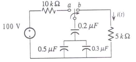
The switch in the circuit shown was on position \(a\) for a long time, and is moved to position \(b\) at time \(t = 0\). The current \(i(t)\) for \(t > 0\) is given by

Question diagram

Open complete paper
16
2009 · Electronics & Communication Engineering · Networks, Signals and Systems · Time and frequency domain analysis of linear circuits
Electronics & Communication Engineering (EC) 2009
The time domain behavior of an \(RL\) circuit is represented by \[L \frac{di}{dt} + Ri = V_o \left(1 + Be^{-\frac{R}{L}t} \sin t \right) u(t).\] For an initial current of \(i(0) = \frac{V_o}{R}\), the steady state value of the current is given by
Open complete paper
17
2009 · Electronics & Communication Engineering · Networks, Signals and Systems · Time and frequency domain analysis of linear circuits
Electronics & Communication Engineering (EC) 2009
An LTI system having transfer function \(\frac{s^2 + 1}{s^2 + 2s + 1}\) and input \(x(t) = \sin(t+1)\) is in steady state. The output is sampled at a rate \(\omega_s\) rad/s to obtain the final output \(\{y(k)\}\). Which of the following is true ?
Open complete paper
18
2009 · Electronics & Communication Engineering · Networks, Signals and Systems · Time and frequency domain analysis of linear circuits
Electronics & Communication Engineering (EC) 2009
The unit step response of an under-damped second order system has steady state value of \(-2\). Which one of the following transfer functions has these properties ?
Open complete paper
19
2010 · Electronics & Communication Engineering · Networks, Signals and Systems · Time and frequency domain analysis of linear circuits
Electronics & Communication Engineering (EC) 2010

For a parallel RLC circuit, which one of the following statements is NOT correct?

Open complete paper
20
2010 · Electronics & Communication Engineering · Networks, Signals and Systems · Time and frequency domain analysis of linear circuits
Electronics & Communication Engineering (EC) 2010
A system with the transfer function \(\frac{Y(s)}{X(s)} = \frac{s}{s+p}\) has an output \(y(t) = \cos\left(2t - \frac{\pi}{3}\right)\) for the input signal \(x(t) = p \cos\left(2t - \frac{\pi}{2}\right)\). Then, the system parameter 'p' is
Open complete paper

Showing 20 of 117 questions