My Cart
Your Cart 0

    Your cart is empty.

  • Total (Amount) ₹0.00
Previous year question hub

Circuit Analysis - Networks, Signals and Systems - Electronics & Communication Engineering Previous Year Questions

Practice Circuit Analysis - Networks, Signals and Systems - Electronics & Communication Engineering previous year questions organised from real papers, with year-wise coverage and clear topic navigation.

26Papers
19Years
100Questions
1Topics

Circuit Analysis question pattern

Every graph below is calculated only from this selection.

Questions by year

Compare question counts across years.

Difficulty distribution

How the classified questions are distributed by difficulty.

Medium 64 64%
Easy 30 30%
Hard 6 6%
Question type distribution

MCQ, numerical, multiple-select and other formats found in these papers.

MCQ 77 77%
Numerical Answer Type (NAT) 20 20%
Fill in the blanks 3 3%

Subject weightage

Top subjects by unique question coverage.

Electronics & Communication Engineering
100 Qs

Most asked topics

Top topics across the included previous year papers.

Networks, Signals and Systems
100 Qs

Subtopic coverage

Top subtopics inside this exact selection.

Circuit Analysis
100 Qs

Paper coverage

Question coverage for the most populated papers. Every active PYP paper remains listed below.

Electronics and Communication Engineering (EC) 2026
2 Qs
Electronics & Communication Engineering (EC) 2025
4 Qs
Electronics & Communication Engineering (EC) 2024
3 Qs
Electronics & Communication Engineering (EC) 2023
3 Qs
Electronics & Communication Engineering (EC) 2022
4 Qs
Electronics & Communication Engineering (EC) 2021
2 Qs
Electronics & Communication Engineering (EC) 2020
3 Qs
Electronics & Communication Engineering (EC) 2019
2 Qs
Electronics & Communication Engineering (EC) 2018
2 Qs
Electronics & Communication Engineering (EC) 2017
3 Qs
Electronics & Communication Engineering (EC) 2017 [Session 2]
2 Qs
Electronics & Communication Engineering (EC) 2016 [Session 2]
2 Qs
Electronics & Communication Engineering (EC) 2016 [Session 3]
2 Qs
Electronics & Communication Engineering (EC) 2016 [Session 1]
1 Qs
Electronics & Communication Engineering (EC) 2014 [Session 4]
5 Qs
Electronics & Communication Engineering (EC) 2014 [Session 1]
4 Qs
Electronics & Communication Engineering (EC) 2013 [Session 2]
8 Qs
Electronics & Communication Engineering (EC) 2013 [Session 4]
7 Qs
Electronics & Communication Engineering (EC) 2013 [Session 1]
6 Qs
Electronics & Communication Engineering (EC) 2013 [Session 3]
6 Qs
Electronics & Communication Engineering (EC) 2012
7 Qs
Electronics & Communication Engineering (EC) 2011
5 Qs
Electronics & Communication Engineering (EC) 2010
3 Qs
Electronics & Communication Engineering (EC) 2009
5 Qs
Electronics & Communication Engineering (EC) 2008
6 Qs
Electronics & Communication Engineering (EC) 2007
3 Qs

Included previous year papers

Newest papers appear first. Search these papers or sort by year and name.

Paper nameYearPDFAttempt
Electronics and Communication Engineering (EC) 20262026
2 questions in this view
2026
Electronics & Communication Engineering (EC) 20252025
4 questions in this view
2025
Electronics & Communication Engineering (EC) 20242024
3 questions in this view
2024
Electronics & Communication Engineering (EC) 20232023
3 questions in this view
2023
Electronics & Communication Engineering (EC) 20222022
4 questions in this view
2022
Electronics & Communication Engineering (EC) 20212021
2 questions in this view
2021
Electronics & Communication Engineering (EC) 20202020
3 questions in this view
2020
Electronics & Communication Engineering (EC) 20192019
2 questions in this view
2019
Electronics & Communication Engineering (EC) 20182018
2 questions in this view
2018
Electronics & Communication Engineering (EC) 20172017
3 questions in this view
2017
Electronics & Communication Engineering (EC) 2017 [Session 2]2017
2 questions in this view
2017
Electronics & Communication Engineering (EC) 2016 [Session 1]2016
1 questions in this view
2016
Electronics & Communication Engineering (EC) 2016 [Session 2]2016
2 questions in this view
2016
Electronics & Communication Engineering (EC) 2016 [Session 3]2016
2 questions in this view
2016
Electronics & Communication Engineering (EC) 2014 [Session 1]2014
4 questions in this view
2014
Electronics & Communication Engineering (EC) 2014 [Session 4]2014
5 questions in this view
2014
Electronics & Communication Engineering (EC) 2013 [Session 1]2013
6 questions in this view
2013
Electronics & Communication Engineering (EC) 2013 [Session 2]2013
8 questions in this view
2013
Electronics & Communication Engineering (EC) 2013 [Session 3]2013
6 questions in this view
2013
Electronics & Communication Engineering (EC) 2013 [Session 4]2013
7 questions in this view
2013
Electronics & Communication Engineering (EC) 20122012
7 questions in this view
2012
Electronics & Communication Engineering (EC) 20112011
5 questions in this view
2011
Electronics & Communication Engineering (EC) 20102010
3 questions in this view
2010
Electronics & Communication Engineering (EC) 20092009
5 questions in this view
2009
Electronics & Communication Engineering (EC) 20082008
6 questions in this view
2008
Electronics & Communication Engineering (EC) 20072007
3 questions in this view
2007

All Circuit Analysis previous year questions

Practice every matching question in batches of 20, with every available option.

1
2007 · Electronics & Communication Engineering · Networks, Signals and Systems · Circuit Analysis
Electronics & Communication Engineering (EC) 2007
An independent voltage source in series with an impedance \(Z_s = R_s + jX_s\) delivers a maximum average power to a load impedance \(Z_L\) when
Open complete paper
2
2007 · Electronics & Communication Engineering · Networks, Signals and Systems · Circuit Analysis
Electronics & Communication Engineering (EC) 2007

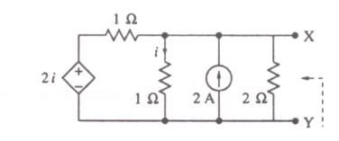
For the circuit shown in the figure, the Thevenin voltage and resistance looking into X-Y are

Question diagram

Open complete paper
3
2007 · Electronics & Communication Engineering · Networks, Signals and Systems · Circuit Analysis
Electronics & Communication Engineering (EC) 2007
In the AC network shown in the figure, the phasor voltage V_AB (in Volts) is

Question diagram

Open complete paper
4
2008 · Electronics & Communication Engineering · Networks, Signals and Systems · Circuit Analysis
Electronics & Communication Engineering (EC) 2008

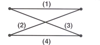
In the following graph, the number of trees (P) and the number of cut-sets (Q) are

Question diagram

Open complete paper
5
2008 · Electronics & Communication Engineering · Networks, Signals and Systems · Circuit Analysis
Electronics & Communication Engineering (EC) 2008
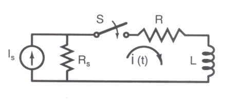
In the following circuit, the switch S is closed at \(t = 0\). The rate of change of current \(\frac{di(t)}{dt}(0^+)\) is given by

Question diagram

Open complete paper
6
2008 · Electronics & Communication Engineering · Networks, Signals and Systems · Circuit Analysis
Electronics & Communication Engineering (EC) 2008

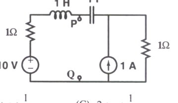
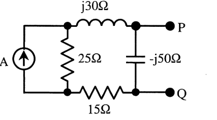
The Thevenin equivalent impedance \(Z_{th}\) between the nodes P and Q in the following circuit is

Question diagram

Open complete paper
7
2008 · Electronics & Communication Engineering · Networks, Signals and Systems · Circuit Analysis
Electronics & Communication Engineering (EC) 2008
The driving point impedance of the following network

is given by \(Z(s) = \frac{0.2s}{s^2 + 0.1s + 2}\). The component values are
Open complete paper
8
2008 · Electronics & Communication Engineering · Networks, Signals and Systems · Circuit Analysis
Electronics & Communication Engineering (EC) 2008
The z-parameter matrix for this network is

Question diagram

Open complete paper
9
2008 · Electronics & Communication Engineering · Networks, Signals and Systems · Circuit Analysis
Electronics & Communication Engineering (EC) 2008
The h-parameter matrix for this network is
Open complete paper
10
2009 · Electronics & Communication Engineering · Networks, Signals and Systems · Circuit Analysis
Electronics & Communication Engineering (EC) 2009
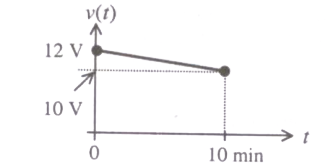
A fully charged mobile phone with a 12 V battery is good for a 10 minute talk-time. Assume that, during the talk-time, the battery delivers a constant current of 2 A and its voltage drops linearly from 12 V to 10 V as shown in the figure. How much energy does the battery deliver during this talk-time ?

Question diagram

Open complete paper
11
2009 · Electronics & Communication Engineering · Networks, Signals and Systems · Circuit Analysis
Electronics & Communication Engineering (EC) 2009
In the interconnection of ideal sources shown in the figure, it is known that the 60 V source is absorbing power.
Which of the following can be the value of the current source \(I\) ?
Open complete paper
12
2009 · Electronics & Communication Engineering · Networks, Signals and Systems · Circuit Analysis
Electronics & Communication Engineering (EC) 2009
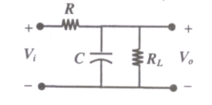
If the transfer function of the following network is \(\frac{V_o(s)}{V_i(s)} = \frac{1}{2 + sCR}\), the value of the load resistance \(R_L\) is

Question diagram

Open complete paper
13
2009 · Electronics & Communication Engineering · Networks, Signals and Systems · Circuit Analysis
Electronics & Communication Engineering (EC) 2009
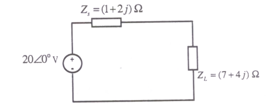
An AC source of RMS voltage 20 V with internal impedance \(Z_s = (1 + 2j) \Omega\) feeds a load of impedance \(Z_L = (7 + 4j) \Omega\) in the figure below. The reactive power consumed by the load is

Question diagram

Open complete paper
14
2009 · Electronics & Communication Engineering · Networks, Signals and Systems · Circuit Analysis
Electronics & Communication Engineering (EC) 2009
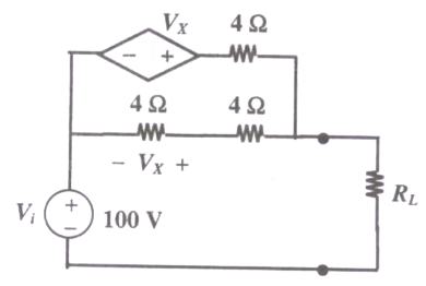
In the circuit shown, what value of \(R_L\) maximizes the power delivered to \(R_L\) ?

Question diagram

Open complete paper
15
2010 · Electronics & Communication Engineering · Networks, Signals and Systems · Circuit Analysis
Electronics & Communication Engineering (EC) 2010

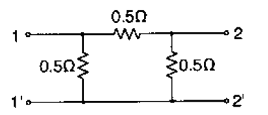
For the two-port network shown below, the short-circuit admittance parameter matrix is

Question diagram

Open complete paper
16
2010 · Electronics & Communication Engineering · Networks, Signals and Systems · Circuit Analysis
Electronics & Communication Engineering (EC) 2010

The current I in the circuit shown is

Question diagram

Open complete paper
17
2010 · Electronics & Communication Engineering · Networks, Signals and Systems · Circuit Analysis
Electronics & Communication Engineering (EC) 2010

In the circuit shown, the power supplied by the voltage source is

Question diagram

Open complete paper
18
2011 · Electronics & Communication Engineering · Networks, Signals and Systems · Circuit Analysis
Electronics & Communication Engineering (EC) 2011

In the circuit shown below, the Norton equivalent current in amperes with respect to the terminals P and Q is

Question diagram

Open complete paper
19
2011 · Electronics & Communication Engineering · Networks, Signals and Systems · Circuit Analysis
Electronics & Communication Engineering (EC) 2011

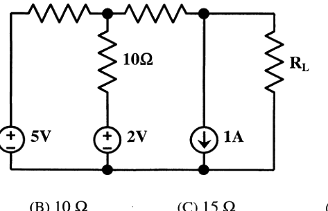
In the circuit shown below, the value of \(R_L\) such that the power transferred to \(R_L\) is maximum is

Question diagram

Open complete paper
20
2011 · Electronics & Communication Engineering · Networks, Signals and Systems · Circuit Analysis
Electronics & Communication Engineering (EC) 2011
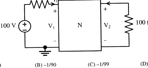
In the circuit shown below, the network N is described by the following Y matrix: $Y = \begin{bmatrix} 0.1\,\text{S} & -0.01\,\text{S} \\ 0.01\,\text{S} & 0.1\,\text{S} \end{bmatrix}$. The voltage gain $\frac{V_2}{V_1}$ is

Question diagram

Open complete paper

Showing 20 of 93 questions