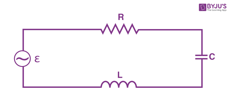
\(\begin{array}{l}Z = \sqrt{R^{2}+\left ( \omega L-\frac{1}{\omega C} \right )^{2}}\end{array} \)
\(\begin{array}{l}Z = \sqrt{15^{2}+\left ( 100\pi (80\times 10^{-3})-\frac{1}{100\pi \times 60\times 10^{-6}} \right )^{2}}\end{array} \)
\(\begin{array}{l}Z = \sqrt{15^{2}+\left ( 25.12-53.08 \right )^{2}}=31.728 \Omega\end{array} \)
I = V/Z = 230/31.728 = 7.25 A
The average power transferred to resistance is given as
PR = I2 R
= (7.25)2 x 15 = 788.44 W
Average power transferred to the capacitor, PC = 0
Average power transferred to the capacitor, PL= 0
Therefore, the total power absorbed by the circuit = PR + PC + PL = 788.44 + 0 + 0 = 788. 44 W
Question 7.20:
A series LCR circuit with L = 0.12 H, C = 480 nF, and R = 23 Ω is connected to a 230 V variable frequency supply.
(a) What is the source frequency for which the current amplitude is maximum? Obtain this maximum value.
(b) What is the source frequency for which the average power absorbed by the circuit is maximum? Obtain the value of this maximum power.
(c) For which frequencies of the source are the power transferred to the circuit half the power at resonant frequency? What is the current amplitude at these frequencies?
(d) What is the Q-factor of the given circuit?
Answer 7.20:
Inductance, L = 0.12 H
Capacitance, C = 480 nF = 480 x 10-9 F
Resistance, R = 23 Ω
Supply voltage, V = 230 V
Peak voltage is given as
Vo = V√2 = 230√2 = 325.22 V
(a) Current flowing the circuit is given by the relation
\(\begin{array}{l}I_{0}=\frac{V_{0}}{\sqrt{R^{2}+\left ( \omega L-\frac{1}{\omega C}\right )^{2}}}\end{array} \)
At resonance, we have
\(\begin{array}{l}\left ( \omega_{_{R}} L-\frac{1}{\omega_{R} C}\right ) = 0\end{array} \)
ωR is the resonance angular frequency
ωR = 1/√LC
= 1/√0.12 x 480 x 10-9 = 4166. 67 rad/s
Resonant frequency, νR = ωR/2π = 4166. 67/2 x 3.14 = 663.48 Hz
Maximum current, (I0)max = V0/R = 325.22/23 = 14.14 A
(b) Maximum average power absorbed by the circuit is
PMax = (1/2) (I0)2max R
= (1/2) x (14.14)2 x 23 = 2300 W
(c) The power transferred to the circuit is half the power at the resonant frequency
P = Vrms Irms cos Φ
= [(Vrms)2/Z ] x (R/Z)
= (Vrms2 x R)/Z2
Pmax = (Vrms)2/Z
Given P = (1/2) Pmax
Therefore, we get
(Vrms2 x R)/Z2 =(Vrms)2/2Z
2R2 = Z2
2R2 = R2 + (XC– XL)2
XC– XL = ± R
Let us take XC– XL = + R
(1/Cω) – Lω = R
1 – LCω2 = RCω
LCω2 + RCω -1 = 0
\(\begin{array}{l}\omega =\frac{-RC+ \sqrt{R^{2}C^{2}-4LC}}{2LC}\end{array} \)
\(\begin{array}{l}\omega =\frac{-23\times 480\times 10^{-9}+ \sqrt{(23\times 480\times 10^{-9})^{2}-4\times 0.12\times 480\times 10^{-9}}}{2\times 0.12\times 480\times 10^{-9}}\end{array} \)
ω = 4263.63 rad/s
Let us consider
XC– XL = – R
(1/Cω) – Lω = – R
1 – LCω2 = RCω
LCω2 – RCω -1 = 0
= (CR)2 – 4 (LC)
Substituting the values, we get a negative value. Therefore, it will not be considered.
So, ω = 4263.63 rad/s
Therefore, 2πf = ω
⇒ f = 4263.63/(2 x 3.14) =4263.63/6.28 = 678.57 Hz
At this frequency, the current frequency is given as,
I’ = (1/√2) x (I0)max
= 14.14/√2 = 10 A
(d) Q factor,
\(\begin{array}{l}Q = \frac{1}{R}\sqrt{\frac{L}{C}}\end{array} \)
\(\begin{array}{l}Q = \frac{1}{23}\sqrt{\frac{0.12}{480\times 10^{-9}}}=21.74\end{array} \)
Question 7.21:
Obtain the resonant frequency and Q-factor of a series LCR circuit with L = 3.0 H, C = 27 µF, and R = 7.4 Ω. It is desired to improve the sharpness of the resonance of the circuit by reducing its ‘full width at half maximum’ by a factor of 2. Suggest a suitable way.
Answer 7.21:
Inductance, L = 3.0 H
Capacitance, C = 27μF = 27 x 10-6 F
Resistance, R = 7.4 Ω
For the LCR series circuit, the resonant frequency of the source is
\(\begin{array}{l}\omega =\frac{1}{\sqrt{LC}}\end{array} \)
\(\begin{array}{l}\omega =\frac{1}{\sqrt{3\times 27\times 10^{-6}}}= 111.11 rad/s\end{array} \)
Q-factor of the series
Q = ωL/R
= (111.11 x 3)/7.4 = 45.04
To improve the sharpness of the resonance of the circuit by reducing its ‘full width at half maximum’ by a factor of 2, we should reduce the resistance to half.
= R/2 = 7.4/2 = 3. 7 Ω
Question 7.22:
Answer the following questions:
(a) In any AC circuit, is the applied instantaneous voltage equal to the algebraic sum of the instantaneous voltages across the series elements of the circuit? Is the same true for RMS voltage?
(b) Why a capacitor is used in the primary circuit of an induction coil?
(c) An applied voltage signal consists of a superposition of a DC voltage and an AC voltage of high frequency. The circuit consists of an inductor and a capacitor in series. Show that the DC signal will appear across C and the AC signal across L.
(d) A choke coil in series with a lamp is connected to a DC line. The lamp is seen to shine brightly. Insertion of an iron core in the choke causes no change in the lamp’s brightness. Predict the corresponding observations if the connection is to an AC line.
(e) Why is choke coils needed in the use of fluorescent tubes with AC mains? Why can we not use an ordinary resistor instead of the choke coil?
Answer 7.22:
(a) Yes, the applied instantaneous voltage is equal to the algebraic sum of the instantaneous voltages across the series elements of the circuit. The same is not true for RMS voltage because voltages across different elements may not be in phase.
(b) When the circuit is broken, the high induced voltage is used to charge the capacitor, thus avoiding sparks, etc.
(c) For a DC signal, the impedance across the inductor is negligible, and the impedance of the capacitor is very high (infinite). So the DC signal appears across the capacitor. For high-frequency AC, the impedance across the inductor is high, and that of a capacitor is low. So, the AC signal appears across the inductor.
(d) For a steady state DC, L has no effect, even if it is increased by an iron core. For AC, the lamp will shine dimly because of the additional impedance of the choke. It will dim further when the iron core is inserted, which increases the choke’s impedance.
(e) A choke coil reduces the voltage across the fluorescent tube without wasting power. A resistor would waste power as heat.
Question 7.23:
A power transmission line feeds input power at 2300 V to a step-down transformer, with its primary windings having 4000 turns. What should be the number of turns in the secondary in order to get output power at 230 V?
Answer 7.23:
The input voltage to the transformer, V1 = 2300 V
Primary windings in the step-down transformer, n1= 4000 turns
Output voltage, V2 = 230 V
Let n2 be the number of turns in the secondary
n2 = (n1 x V2)/V1
= (4000 x 230)/2300 = 400 turns
So, the number of turns in the secondary windings is 400.
Question 7.24:
At a hydroelectric power plant, the water pressure head is at the height of 300 m, and the water flow available is 100 m3s–1. If the turbine generator efficiency is 60%, estimate the electric power available from the plant (g = 9.8 ms–2).
Answer 7.24:
h = 300 m
Volume of water flowing = 100 m3s–1
Density of water, ρ = 1000 kg/m3
Electric power, P= hρgAv = hρgβ
Here, β = Av (Volume of water flowing per second, β= 100 m3s–1 )
⇒ P = hρgβ = 300 x 1000 x 9.8 x 100 = 29.4 x 10⁷W
The efficiency of the turbine generator = 60%
Electric power available for the plant = (29.4 x 107 x 60)/100
= 176.4 x 10⁶ W
Question 7.25:
A small town with a demand of 800 kW of electric power at 220 V is situated 15 km away from an electric plant generating power at 440 V.
The resistance of the two wirelines carrying power is 0.5 Ω per km. The town gets power from the line through a 4000-220 V step-down transformer at a substation in the town.
(a) Estimate the line power loss in the form of heat.
(b) How much power must the plant supply, assuming there is negligible power loss due to leakage?
(c) Characterise the step-up transformer at the plant.
Answer 7.25:
Power required , P = 800 kW = 800 x 103 W
Power = Voltage x Current
⇒ 800 x 103 = 4000 x I
Therefore, RMS current in the line, I = (800 x 103 )/4000
I = 200 A
Total resistance of the two wire line, R = 2 x 15 x 0.5 = 15 Ω
(a) Line power loss = I2 R= (200)2 x 15 = 60 x 104 W = 600 kW
(b) Power supply to the plant= 800 kW + 600 kW= 1400 kW
(c) Voltage drop on the line = I R = 200 x 15 = 3000 V
Transmission voltage = 4000 V + 3000 V= 7000 V
The step-up transformer at the plant is 440 V – 7000 V
Question 7.26:
Do the same exercise as above with the replacement of the earlier transformer by a 40,000-220 V step-down transformer (Neglect, as before, leakage losses though this may not be a good assumption
any longer because of the very high voltage transmission involved). Hence, explain why high-voltage transmission is preferred.
Answer 7.26:
The RMS current in the line, I = (800 x 103 )/40,000
I = 20 A
Total resistance of the two-wire line, R = 2 x 15 x 0.5 = 15 Ω
(a) Line power loss = I2 R= (20)2 x 15 = 60 x 102 W = 6 kW
(b) Power supply to the plant= 800 kW + 6 kW= 806 kW
(c) Voltage drop on the line = I R = 20 x 15 = 300 V
The step-up transformer is 440 V – 40 V=300 V. It is clear that percentage power loss is greatly reduced by high voltage transmission. In Question 7.25, this power loss is (600/1400) × 100 = 43%. Here, it is only (6/806) × 100 = 0.74%.
We have provided NCERT Solutions for Class 12 Physics Chapter 7 Alternating Current for students to strengthen their knowledge on the topic of Alternating Current. With the above NCERT Class 12 Physics Solutions for Chapter 7 Alternating Current PDF, students can learn the topic easily with the help of questions and solved answers.
Class 12 Physics NCERT Solutions for Chapter 7 Alternating Current
Alternating Current is a crucial chapter under the Unit – Electromagnetic Induction and Alternating Currents in Class 12 Physics and is formulated as per the latest CBSE Syllabus 2023-24. Students must be well-versed in this chapter to score high marks in the Class 12 board examinations. Hence,