My Cart
Your Cart 0

    Your cart is empty.

  • Total (Amount) ₹0.00
NCERT · Class 12 · Physics

Chapter 14: Semiconductor Electronics: Materials, Devices and Simple Circuits

Practice each question, then open the answer or worked solution.

Questions

15 questions
Q11Written answer

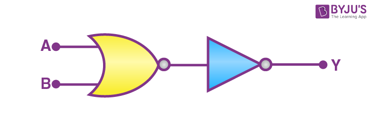
You are given the two circuits as shown in Fig. 14.36. Show that
circuit (a) acts as OR gate while circuit (b) acts as AND gate.

a)
NCERT Solutions for Class 12 Physics Chapter 14 Semiconductor Electronics Materials Question 11 Image 1
b)

Show solutionHide solution
Worked solution

(a) Input for the circuit: A and B

Output for the circuit: Y

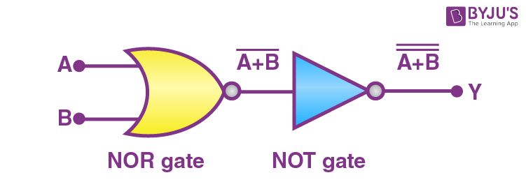
Here, the left half of the circuit works as the NOR gate, while if we look at the right half of the circuit, then it is a NOT gate.

We can show it in the figure as:
NCERT Solutions for Class 12 Physics Chapter 14 Semiconductor Electronics Materials Question 11 Solution Image 1

Now, the output for the NOR gate =

\(\begin{array}{l}\overline{A + B}\end{array} \)

We are giving the output from NOR gate to the input at the NOT gate. So, its output will be

\(\begin{array}{l}\overline{\overline{A + B}}\end{array} \)
\(\begin{array}{l}∴ Y = A + B\end{array} \)

Hence, this circuit functions as an OR Gate.

(b) Input for the circuit: A and B

Output for the circuit: Y

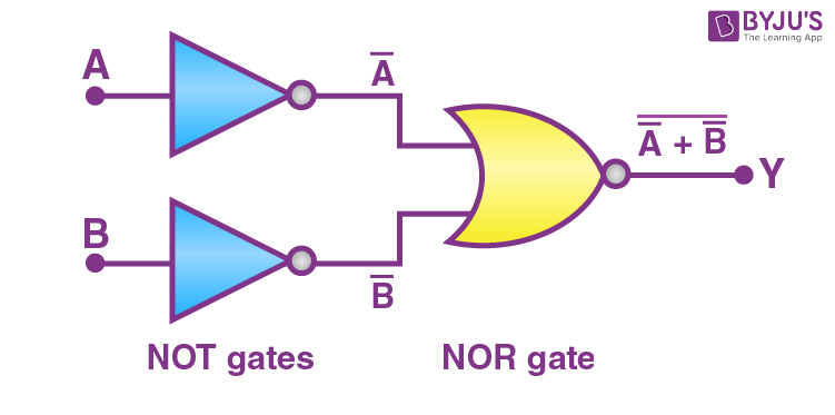
We can observe from the figure that the output from the first half of the circuits goes to the input of the next half, which is working as NOR gate.
NCERT Solutions for Class 12 Physics Chapter 14 Semiconductor Electronics Materials Question 11 Solution Image 2

Hence, the output of the given circuit can be written as

\(\begin{array}{l}Y = \overline{\bar{A} + \bar{B}} = \bar{\bar{A}}.\bar{\bar{B}} = A.B\end{array} \)

Hence, this circuit functions as an AND gate.
Q12Written answer

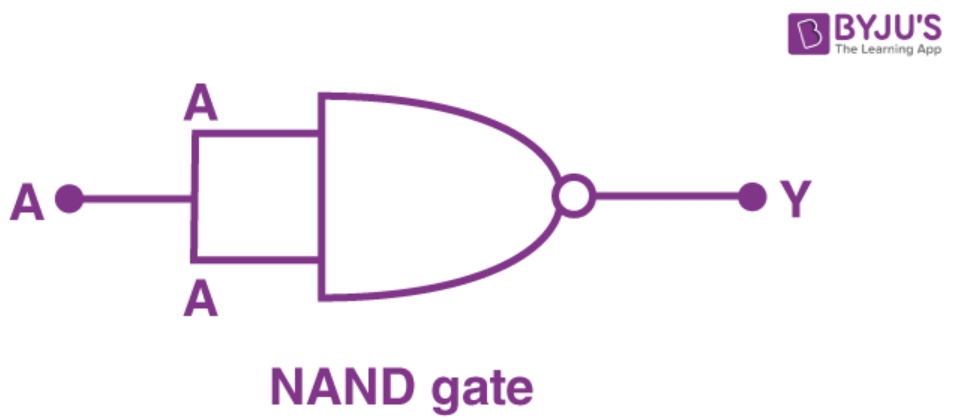
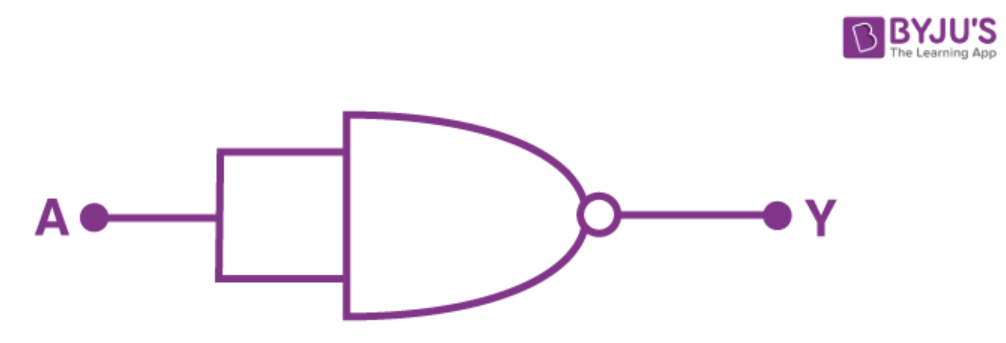
Write the truth table for a NAND gate connected as given in
Fig. 14.37

NCERT Solutions for Class 12 Physics Chapter 14 Semiconductor Electronics Materials Question 12

Hence, identify the exact logic operation carried out by this circuit.

Show solutionHide solution
Worked solution

From the figure, we know A is the input, and we are getting an output B.

NCERT Solutions for Class 12 Physics Chapter 14 Semiconductor Electronics Materials Question 12 Solution Image 1

Hence, the output can be written as

\(\begin{array}{l}Y = \overline{ A . A } = \bar{A} + \bar{A} = \bar{A}\end{array} \)

We can make the truth table for equation (1) as:

A Y=
\(\begin{array}{l}\bar{A}\end{array} \)
0 1
1 0

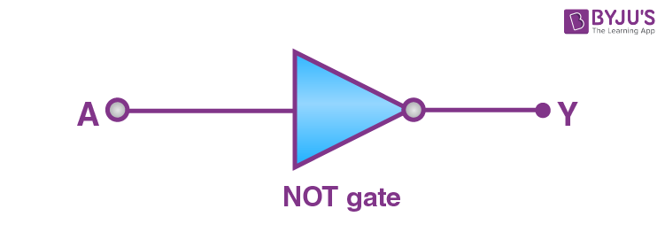
Below is the symbol of the NOT gate:

NCERT Solutions for Class 12 Physics Chapter 14 Semiconductor Electronics Materials Question 12 Solution Image 2

Q13Written answer

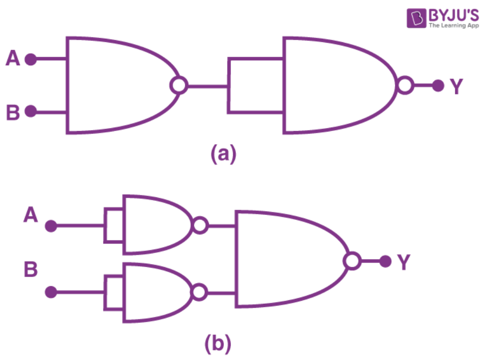
You are given two circuits, as shown in Figure, which consist of NAND gates. Identify the logic operation carried out by the two circuits.

NCERT Solutions for Class 12 Physics Chapter 14 Semiconductor Electronics Question 13

Show solutionHide solution
Worked solution

(a) The Boolean expression for NAND gate is

\(\begin{array}{l}Y=\overline{AB}\end{array} \)

Let Y’ be the output of the NAND gate.

Therefore, the final output of the combination, 

\(\begin{array}{l}Y = \overline{Y’.Y’}\end{array} \)


\(\begin{array}{l}\mathbf{Y}=\overline{\overline{\mathbf{A . B}} \cdot \overline{\mathbf{A . B}}}\end{array} \)


\(\begin{array}{l}Y = \overline{A.B}+\overline{A.B}\end{array} \)

Y = A.B

The given circuit acts as an AND gate.

(b) Boolean expression for NOT gate is 

\(\begin{array}{l}Y = \bar{A}\end{array} \)

The output Y1 of the first NOT gate is 

\(\begin{array}{l}Y_{1} = \bar{A}\end{array} \)


The output Y2 of the second NOT gate is 

\(\begin{array}{l}Y_{2} = \bar{B}\end{array} \)

The output of the combination


\(\begin{array}{l}Y = \overline{Y_{1}.Y_{2}}\end{array} \)


\(\begin{array}{l}Y = \overline{\bar{A}.\bar{B}}\end{array} \)


\(\begin{array}{l}Y = \bar{\bar{A}}+\bar{\bar{B}}\end{array} \)

Y = A + B

This is the Boolean expression for the OR gate.


Q14Written answer

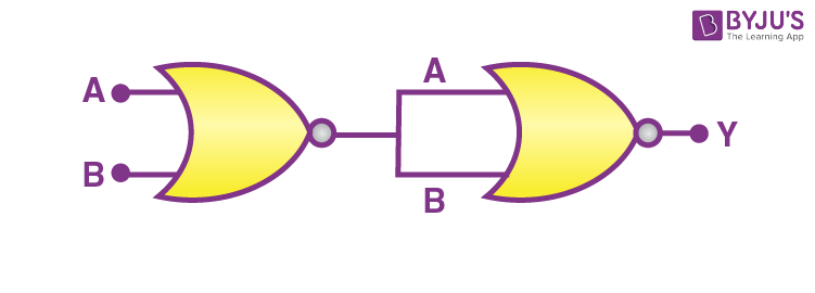
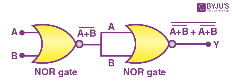
Write the truth table for the circuit given in Fig. 14.39 below, consisting
of NOR gates and identify the logic operation (OR, AND, NOT) which
this circuit is performing

  NCERT Solutions for Class 12 Physics Chapter 14 Semiconductor Electronics Materials Question 14(Hint: A = 0, B = 1, then A and B inputs of the second NOR gate will be 0 and hence, Y=1. Similarly, work out the values of Y for other combinations of A and B. Compare with the truth table of OR, AND, NOT gates and find the correct one.)
Show solutionHide solution
Worked solution

Input for the circuit: A and B

Output from the first circuit (i.e., NOR gate) is

\(\begin{array}{l}\overline{A + B}\end{array} \)

From the figure, we can observe that the input for the second gate is automatically the output from the first one.

NCERT Solutions for Class 12 Physics Chapter 14 Semiconductor Electronics Materials Question 14 Solution

Therefore, the output obtained from this combination is given as:

\(\begin{array}{l}Y = \overline{\overline{A + B} + \overline{A + B} } = \overline{ \bar{ A } . \bar{ B }} + \overline{ \bar{ A } . \bar{ B }} \\ \\ = \overline{ \bar{ A } . \bar{ B }} = \bar{ \bar{ A } } + \bar{ \bar{ B } } = A + B\end{array} \)

Following is the truth table for the given operation:

A B Y (= A + B)
0 0 0
0 1 1
1 0 1
1 1 1

This is the truth table of an OR gate.

Therefore, this circuit functions as an OR gate.

Q15Written answer

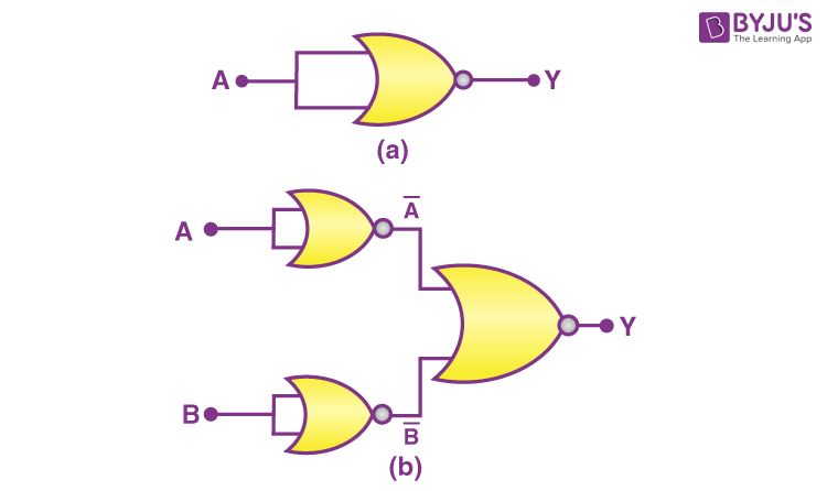
Write the truth table for the circuits given in the Figure consisting of NOR gates only. Identify the logic operations (OR, AND, NOT) performed by the two circuits.

NCERT Solutions for Class 12 Physics Chapter 14 Semiconductor Electronics Question 15

Show solutionHide solution
Worked solution

In figure (a), A acts as the two inputs of the NOR gate, and Y is the output. Hence, the output of the circuit is

\(\begin{array}{l}\overline{\mathrm{A}+\mathrm{A}}\end{array} \)

So, the output 

\(\begin{array}{l}Y= \overline{\mathrm{A}}\end{array} \)

Therefore, the gate is a NOT gate.

The truth table is given as

A
\(\begin{array}{l}Y= \overline{\mathrm{A}}\end{array} \)
0 1
1 0

(b) In figure (b),  A and B are the inputs, and Y is the output of the given circuit. By using the result obtained in solution (a), we can infer that the outputs of the first two NOR gates are

\(\begin{array}{l}\overline{\mathrm{A}}\end{array} \)
\(\begin{array}{l}\overline{\mathrm{B}}\end{array} \)
\(\begin{array}{l}\mathbf{Y}=\overline{\overline{\mathbf{A}}+\overline{\mathbf{B}}}=\mathbf{A} . \mathbf{B}\end{array} \)
A B Y= A.B
0 0 0
0 1 0
1 0 0
1 1 1
Class 12 Physics NCERT Solutions for Chapter 14 Semiconductor Electronics

Chapter 14 Semiconductor Electronics of Class 12 Physics, is designed as per the current CBSE Syllabus 2023-24. In this chapter’s