My Cart
Your Cart 0

    Your cart is empty.

  • Total (Amount) ₹0.00
NCERT · Class 10 · Science

Chapter 12: Magnetic Effects of Electric Current

Practice each question, then open the answer or worked solution.

Exercises · Page 240

Textbook page 240 · 17 questions
Q11Written answer

Draw a labelled diagram of an electric motor. Explain its principle and working. What is the function of a split ring in an electric motor?

Show solutionHide solution
Worked solution

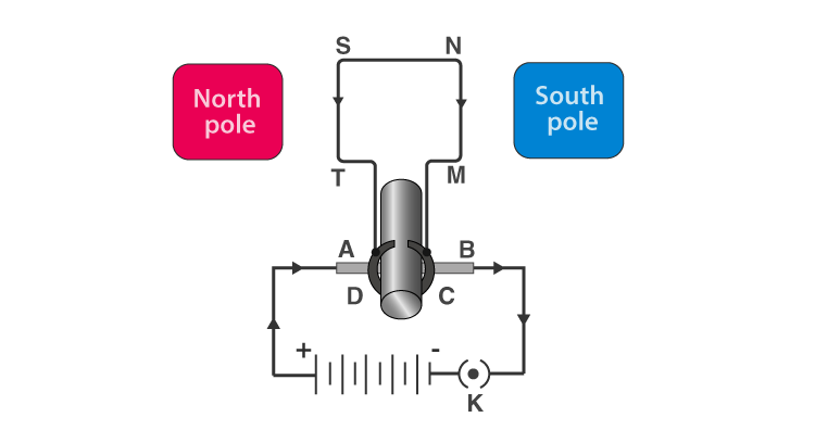
An electric motor is a device that converts electrical energy to mechanical energy. It works on the principle of the magnetic effect of current. The figure listed below shows a simple electric motor.
NCERT Solutions Class 10 Science Chapter 13 - 5

When current is made to flow through the coil MNST by closing the switch, the coil starts to rotate in the anticlockwise direction. This is due to the downward force acting on the length MN and simultaneously an upward force acting along the length ST. As a result of which, the coil rotates in the anticlockwise direction. Current in the length MN flows from M to N, and the magnetic fields act from left to right normal to the length MN. According to Fleming’s Left-Hand rule, a downward force acts along the length MN. Similarly, the current along the length ST flows from S to T and the magnetic field acts from left to right. Therefore, an upward force acts along the length ST. These two forces together cause the coil to rotate anti-clockwise. After half a rotation, the position of MN and ST interchange. The half-ring C comes in contact with brush B and the half-ring D comes in contact with rush C. Hence the direction of current in the coil MNST gets reversed.
Q12Written answer

Name some devices in which electric motors are used.

Show solutionHide solution
Worked solution

A few devices in which electric motors are used are:

  • Electric fans
  • Water pumps
  • Mixers
  • Washing machines
Q13Written answer

A coil of insulated copper wire is connected to a galvanometer. What will happen if a bar magnet is (i) pushed into the coil, (ii) withdrawn from inside the coil, (iii) held stationary inside the coil?

Show solutionHide solution
Worked solution

(i) When a bar magnet is pushed into the coil, a current is induced in the coil momentarily. As a result, the galvanometer deflects in a particular direction momentarily.

(ii) When the bar magnet is withdrawn from inside the coil, a current is induced momentarily but in the opposite direction, and the galvanometer deflects in the opposite direction momentarily.

(iii) When the bar magnet is held stationary inside the coil, no current will be induced. As a result, there will be no deflection in the galvanometer.

Q14Written answer

Two circular coils A and B are placed closed to each other. If the current in the coil A is changed, will some current be induced in the coil B? Give reason.

Show solutionHide solution
Worked solution

When the current in coil A changes, the magnetic field associated with it also changes. As a result, the magnetic field around coil B undergoes change. The change in the magnetic field of coil B induces a current in it.

Q15Written answer

State the rule to determine the direction of a (i) magnetic field produced around a straight conductor-carrying current, (ii) force experienced by a current-carrying straight conductor placed in a magnetic field which is perpendicular to it, and (iii) current induced in a coil due to its rotation in a magnetic field.

Show solutionHide solution
Worked solution

(i) The rule used to determine the direction of the magnetic field produced around a straight conductor-carrying current is Maxwell’s right-hand thumb rule.

(ii) The rule used to determine the force experienced by a current-carrying straight conductor placed in a magnetic field which is perpendicular to it is the Fleming’s left hand rule.

(iii) The rule used to determine the current induced in a coil due to its rotation in a magnetic field is Fleming’s right-hand rule.

Q16Written answer

Explain the underlying principle and working of an electric generator by drawing a labelled diagram. What is the function of brushes?

Show solutionHide solution
Worked solution

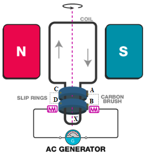
The electric generator converts mechanical energy into electrical energy. The working principle of the electric generator is electromagnetic induction. It generates electricity by rotating a coil in the magnetic field. The figure below shows the construction of a simple AC generator.

NCERT Solutions Class 10 Science Chapter 13 - 6

In the diagram,

A and B are brushes.

C and D are slip rings.

X is the axle.

G is the galvanometer.

When the axle X is rotated clockwise, MN moves upwards while ST moves downward. The movement of MN and ST in the magnetic field results in the production of electric current due to electromagnetic induction. MN moves upwards, and the magnetic fields act from left to right. Therefore, according to Fleming’s right hand rule, the direction of the induced current will be from M to N along the length MN. Similarly, the direction of the induced current will be from S to T along the length ST. The direction of the current in the coil is MNST. Hence, the galvanometer shows a deflection in a particular direction.

After half a rotation, length MN starts moving downwards while the length ST starts moving upwards. Now, the direction of the induced current reverses to TSNM. Since the direction of the induced current reverses every half rotation, the current induced is known as alternating current.

Function of Brushes

Brushes are kept pressed onto two slip rings separately. The outer ends of the brushes are connected to the galvanometer. Thus, brushes help in transferring current from the coil to the external circuit.

Q17Written answer
  1. When does an electric short circuit occur?
Show solutionHide solution
Worked solution

Solution coming soon.