My Cart
Your Cart 0

    Your cart is empty.

  • Total (Amount) ₹0.00
Previous year question hub

LTI Systems and Digital Filters - Signals and Systems - Instrumentation Engineering Previous Year Questions

Practice LTI Systems and Digital Filters - Signals and Systems - Instrumentation Engineering previous year questions organised from real papers, with year-wise coverage and clear topic navigation.

20Papers
17Years
65Questions
1Topics

LTI Systems and Digital Filters question pattern

Every graph below is calculated only from this selection.

Questions by year

Year-wise coverage for LTI Systems and Digital Filters. Each bar uses a separate theme-derived color.

Difficulty distribution

How the classified questions are distributed by difficulty.

Easy 48 73.8%
Medium 16 24.6%
Hard 1 1.5%
Question type distribution

MCQ, numerical, multiple-select and other formats found in these papers.

MCQ 54 83.1%
Numerical Answer Type (NAT) 7 10.8%
MSQ 3 4.6%
Fill in the blanks 1 1.5%

Subject weightage

Top subjects by unique question coverage.

Instrumentation Engineering
65 Qs

Most asked topics

Top topics across the included previous year papers.

Signals and Systems
65 Qs

Subtopic coverage

Top subtopics inside this exact selection.

LTI Systems and Digital Filters
65 Qs

Paper coverage

Question coverage for the most populated papers. Every active PYP paper remains listed below.

Instrumentation Engineering (IN) 2026
1 Qs
Instrumentation Engineering (IN) 2025
2 Qs
Instrumentation Engineering (IN) 2024
1 Qs
Instrumentation Engineering (IN) 2023
2 Qs
Instrumentation Engineering (IN) 2022
2 Qs
Instrumentation Engineering (IN) 2021
5 Qs
Instrumentation Engineering (IN) 2020
2 Qs
Instrumentation Engineering (IN) 2019
2 Qs
Instrumentation Engineering (IN) 2018
3 Qs
Instrumentation Engineering (IN) 2017
1 Qs
Instrumentation Engineering (IN) 2016
2 Qs
Instrumentation Engineering (IN) 2014
5 Qs
Instrumentation Engineering (IN) 2013 [Session 2]
6 Qs
Instrumentation Engineering (IN) 2013 [Session 3]
6 Qs
Instrumentation Engineering (IN) 2013 [Session 4]
6 Qs
Instrumentation Engineering (IN) 2013 [Session 1]
5 Qs
Instrumentation Engineering (IN) 2011
3 Qs
Instrumentation Engineering (IN) 2010
3 Qs
Instrumentation Engineering (IN) 2009
4 Qs
Instrumentation Engineering (IN) 2008
4 Qs

Included previous year papers

Newest papers appear first. Sort by year, question coverage or name.

PaperYear / sessionQuestions in this viewOpen
Instrumentation Engineering (IN) 202620261View paper
Instrumentation Engineering (IN) 202520252View paper
Instrumentation Engineering (IN) 202420241View paper
Instrumentation Engineering (IN) 202320232View paper
Instrumentation Engineering (IN) 202220222View paper
Instrumentation Engineering (IN) 202120215View paper
Instrumentation Engineering (IN) 202020202View paper
Instrumentation Engineering (IN) 201920192View paper
Instrumentation Engineering (IN) 201820183View paper
Instrumentation Engineering (IN) 201720171View paper
Instrumentation Engineering (IN) 201620162View paper
Instrumentation Engineering (IN) 201420145View paper
Instrumentation Engineering (IN) 2013 [Session 1]20135View paper
Instrumentation Engineering (IN) 2013 [Session 2]20136View paper
Instrumentation Engineering (IN) 2013 [Session 3]20136View paper
Instrumentation Engineering (IN) 2013 [Session 4]20136View paper
Instrumentation Engineering (IN) 201120113View paper
Instrumentation Engineering (IN) 201020103View paper
Instrumentation Engineering (IN) 200920094View paper
Instrumentation Engineering (IN) 200820084View paper

All LTI Systems and Digital Filters previous year questions

Practice every matching question in batches of 20, with every available option.

1
2009 · Instrumentation Engineering · Signals and Systems · LTI Systems and Digital Filters
Instrumentation Engineering (IN) 2009
A linear time-invariant causal system has a frequency response given in polar form as \[\frac{1}{\sqrt{1+\omega^2}} \angle -\tan^{-1} \omega\]. For input x(t) = \sin t , the output is
Open complete paper
2
2009 · Instrumentation Engineering · Signals and Systems · LTI Systems and Digital Filters
Instrumentation Engineering (IN) 2009
An analog signal is sampled at 9 kHz. The sequence so obtained is filtered by an FIR filter with transfer function \(H(z) = 1 - z^{-6}\). One of the analog frequencies for which the magnitude response of the filter is zero is
Open complete paper
3
2009 · Instrumentation Engineering · Signals and Systems · LTI Systems and Digital Filters
Instrumentation Engineering (IN) 2009
The transfer function \(H(z)\) of a fourth-order linear phase FIR system is given by \(H(z) = (1 + 2z^{-1} + 3z^{-2}) G(z)\). Then \(G(z)\) is
Open complete paper
4
2009 · Instrumentation Engineering · Signals and Systems · LTI Systems and Digital Filters
Instrumentation Engineering (IN) 2009
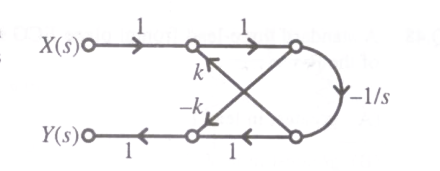
A filter is represented by the signal flow graph shown in the figure. Its input is \(x(t)\) and output is \(y(t)\). The transfer function of the filter is

Question diagram

Open complete paper
5
2010 · Instrumentation Engineering · Signals and Systems · LTI Systems and Digital Filters
Instrumentation Engineering (IN) 2010
\(H(z)\) is a discrete rational transfer function. To ensure that both \(H(z)\) and its inverse are stable its
Open complete paper
6
2010 · Instrumentation Engineering · Signals and Systems · LTI Systems and Digital Filters
Instrumentation Engineering (IN) 2010
The input \(x(t)\) and the corresponding output \(y(t)\) of a system are related by \(y(t) = \int_{-\infty}^{5t} x(\tau) d\tau\). The system is
Open complete paper
7
2010 · Instrumentation Engineering · Signals and Systems · LTI Systems and Digital Filters
Instrumentation Engineering (IN) 2010
A digital filter having a transfer function \(H(z) = \frac{p_0 + p_1 z^{-1} + p_2 z^{-2}}{1 + d_1 z^{-1} + d_2 z^{-2}}\) is implemented using Direct Form – I and Direct Form – II realizations of IIR structure. The number of delay units required in Direct Form – I and Direct Form – II realizations are, respectively
Open complete paper
8
2011 · Instrumentation Engineering · Signals and Systems · LTI Systems and Digital Filters
Instrumentation Engineering (IN) 2011
Shown below is the pole-zero plot of a digital filter. Which one of the following statements is TRUE?
Open complete paper
9
2011 · Instrumentation Engineering · Signals and Systems · LTI Systems and Digital Filters
Instrumentation Engineering (IN) 2011
Consider a system with input \(x(t)\) and output \(y(t)\) related as follows \(y(t) = \frac{d}{dt} \{e^{-t} x(t)\}\). Which one of the following statements is TRUE?
Open complete paper
10
2011 · Instrumentation Engineering · Signals and Systems · LTI Systems and Digital Filters
Instrumentation Engineering (IN) 2011
Consider the difference equation y[n] - 1/3 y[n-1] = x[n] and suppose that x[n] = (1/2)ⁿ u[n]. Assuming the condition of initial rest, the solution for y[n], n ≥ 0 is
Open complete paper
11
2013 · Instrumentation Engineering · Signals and Systems · LTI Systems and Digital Filters
Instrumentation Engineering (IN) 2013 [Session 1]
Two systems with impulse responses $h_1(t)$ and $h_2(t)$ are connected in cascade. Then the overall impulse response of the cascaded system is given by
Open complete paper
12
2013 · Instrumentation Engineering · Signals and Systems · LTI Systems and Digital Filters
Instrumentation Engineering (IN) 2013 [Session 1]
Which one of the following statements is NOT TRUE for a continuous time causal and stable LTI system?
Open complete paper
13
2013 · Instrumentation Engineering · Signals and Systems · LTI Systems and Digital Filters
Instrumentation Engineering (IN) 2013 [Session 1]
The discrete-time transfer function \(\frac{1-2z^{-1}}{1-0.5z^{-1}}\) is
Open complete paper
14
2013 · Instrumentation Engineering · Signals and Systems · LTI Systems and Digital Filters
Instrumentation Engineering (IN) 2013 [Session 1]
The impulse response of a system is \(h(t) = t u(t)\) . For an input \(u(t-1)\) , the output is
Open complete paper
15
2013 · Instrumentation Engineering · Signals and Systems · LTI Systems and Digital Filters
Instrumentation Engineering (IN) 2013 [Session 1]
The impulse response of a continuous time system is given by \(h(t) = \delta(t-1) + \delta(t-3)\). The value of the step response at \(t = 2\) is
Open complete paper
16
2013 · Instrumentation Engineering · Signals and Systems · LTI Systems and Digital Filters
Instrumentation Engineering (IN) 2013 [Session 2]
The impulse response of a system is \(h(t)=t u(t)\). For an input \(u(t-1)\), the output is
Open complete paper
17
2013 · Instrumentation Engineering · Signals and Systems · LTI Systems and Digital Filters
Instrumentation Engineering (IN) 2013 [Session 2]
Two systems with impulse responses \( h_1(t) \) and \( h_2(t) \) are connected in cascade. Then the overall impulse response of the cascaded system is given by
Open complete paper
18
2013 · Instrumentation Engineering · Signals and Systems · LTI Systems and Digital Filters
Instrumentation Engineering (IN) 2013 [Session 2]
Assuming zero initial condition, the response \( y(t) \) of the system given below to a unit step input \( u(t) \) is
Open complete paper
19
2013 · Instrumentation Engineering · Signals and Systems · LTI Systems and Digital Filters
Instrumentation Engineering (IN) 2013 [Session 2]
The impulse response of a continuous time system is given by \( h(t) = \delta(t-1) + \delta(t-3) \). The value of the step response at \( t = 2 \) is
Open complete paper
20
2013 · Instrumentation Engineering · Signals and Systems · LTI Systems and Digital Filters
Instrumentation Engineering (IN) 2013 [Session 3]
Assuming zero initial condition, the response \(y(t)\) of the system given below to a unit step input \(u(t)\) is
Open complete paper

Showing 20 of 57 questions