My Cart
Your Cart 0

    Your cart is empty.

  • Total (Amount) ₹0.00
Previous year question hub

Bridges and Electrical Quantity Measurement - Measurements - Instrumentation Engineering Previous Year Questions

Practice Bridges and Electrical Quantity Measurement - Measurements - Instrumentation Engineering previous year questions organised from real papers, with year-wise coverage and clear topic navigation.

18Papers
18Years
49Questions
1Topics

Bridges and Electrical Quantity Measurement question pattern

Every graph below is calculated only from this selection.

Questions by year

Year-wise coverage for Bridges and Electrical Quantity Measurement. Each bar uses a separate theme-derived color.

Difficulty distribution

How the classified questions are distributed by difficulty.

Medium 30 61.2%
Easy 19 38.8%

Question type distribution

MCQ, numerical, multiple-select and other formats found in these papers.

MCQ 24 49%
Numerical Answer Type (NAT) 18 36.7%
Fill in the blanks 6 12.2%
MSQ 1 2%

Subject weightage

Top subjects by unique question coverage.

Instrumentation Engineering
49 Qs

Most asked topics

Top topics across the included previous year papers.

Measurements
49 Qs

Subtopic coverage

Top subtopics inside this exact selection.

Bridges and Electrical Quantity Measurement
49 Qs

Paper coverage

Question coverage for the most populated papers. Every active PYP paper remains listed below.

Instrumentation Engineering (IN) 2026
1 Qs
Instrumentation Engineering (IN) 2025
5 Qs
Instrumentation Engineering (IN) 2024
1 Qs
Instrumentation Engineering (IN) 2023
3 Qs
Instrumentation Engineering (IN) 2022
4 Qs
Instrumentation Engineering (IN) 2021
2 Qs
Instrumentation Engineering (IN) 2020
2 Qs
Instrumentation Engineering (IN) 2019
4 Qs
Instrumentation Engineering (IN) 2018
2 Qs
Instrumentation Engineering (IN) 2017
5 Qs
Instrumentation Engineering (IN) 2016
4 Qs
Instrumentation Engineering (IN) 2014
2 Qs
Instrumentation Engineering (IN) 2013 [Session 1]
1 Qs
Instrumentation Engineering (IN) 2011
4 Qs
Instrumentation Engineering (IN) 2010
1 Qs
Instrumentation Engineering (IN) 2009
1 Qs
Instrumentation Engineering (IN) 2008
4 Qs
Instrumentation Engineering (IN) 2007
3 Qs

Included previous year papers

Newest papers appear first. Sort by year, question coverage or name.

PaperYear / sessionQuestions in this viewOpen
Instrumentation Engineering (IN) 202620261View paper
Instrumentation Engineering (IN) 202520255View paper
Instrumentation Engineering (IN) 202420241View paper
Instrumentation Engineering (IN) 202320233View paper
Instrumentation Engineering (IN) 202220224View paper
Instrumentation Engineering (IN) 202120212View paper
Instrumentation Engineering (IN) 202020202View paper
Instrumentation Engineering (IN) 201920194View paper
Instrumentation Engineering (IN) 201820182View paper
Instrumentation Engineering (IN) 201720175View paper
Instrumentation Engineering (IN) 201620164View paper
Instrumentation Engineering (IN) 201420142View paper
Instrumentation Engineering (IN) 2013 [Session 1]20131View paper
Instrumentation Engineering (IN) 201120114View paper
Instrumentation Engineering (IN) 201020101View paper
Instrumentation Engineering (IN) 200920091View paper
Instrumentation Engineering (IN) 200820084View paper
Instrumentation Engineering (IN) 200720073View paper

All Bridges and Electrical Quantity Measurement previous year questions

Practice every matching question in batches of 20, with every available option.

1
2009 · Instrumentation Engineering · Measurements · Bridges and Electrical Quantity Measurement
Instrumentation Engineering (IN) 2009

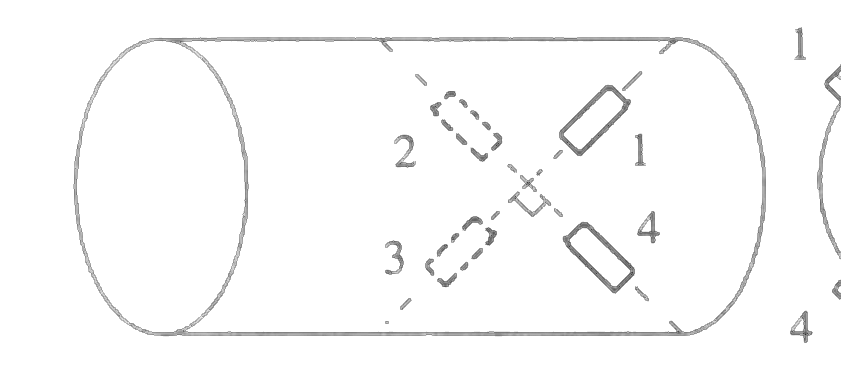
Four strain gauges are fixed on a cylindrical shaft to measure torque, as shown in the figure. A correct way to place these gauges in the bridge is

Open complete paper
2
2010 · Instrumentation Engineering · Measurements · Bridges and Electrical Quantity Measurement
Instrumentation Engineering (IN) 2010
The resistance required to convert the 100 μA ammeter into a 1A full scale dc ammeter is
Open complete paper
3
2011 · Instrumentation Engineering · Measurements · Bridges and Electrical Quantity Measurement
Instrumentation Engineering (IN) 2011
The temperature of a furnace is monitored at a distance of 50 m away. The temperature transmitter has a range of 0−500°C and provides 4−20 mA current output. The measured temperature and the output current have a straight line relationship with positive slope. The temperature is determined from the voltage measured across a resistance of 500Ω in the current loop. If the voltage measured across the resistance is 4 V, the temperature of the furnace is
Open complete paper
4
2011 · Instrumentation Engineering · Measurements · Bridges and Electrical Quantity Measurement
Instrumentation Engineering (IN) 2011
A differential push-pull type capacitive displacement sensor (nominal capacitance \(C_0 = 0.01 μF\)) is connected in two adjacent arms of an ac bridge in such a way that the output voltage of the bridge is independent of the frequency of the supply voltage. Supply to the bridge is 1V at 1 kHz, and two equal resistances (\(R = 3.9 kΩ\)) are placed in the other two arms of the bridge. The bridge sensitivity is

Question diagram

Open complete paper
5
2011 · Instrumentation Engineering · Measurements · Bridges and Electrical Quantity Measurement
Instrumentation Engineering (IN) 2011
In the Wheatstone bridge shown below, when the resistance R₁ increases by 1 Ω, the current through the galvanometer is (consider the Thevenin equivalent resistance of the bridge in the calculations)
Open complete paper
6
2011 · Instrumentation Engineering · Measurements · Bridges and Electrical Quantity Measurement
Instrumentation Engineering (IN) 2011

The ideal opamp based circuit shown below acts as a

Open complete paper
7
2013 · Instrumentation Engineering · Measurements · Bridges and Electrical Quantity Measurement
Instrumentation Engineering (IN) 2013 [Session 1]

The differential amplifier is connected as shown in Fig. (b) above to a single strain gage bridge. Let the strain gage resistance vary around its no-load resistance R by ±1%. Assume the input impedance of the amplifier to be high compared to the equivalent source resistance of the bridge, and the common mode characteristic to be as obtained above. The output voltage in mV varies approximately from

Question diagram

Open complete paper
8
2014 · Instrumentation Engineering · Measurements · Bridges and Electrical Quantity Measurement
Instrumentation Engineering (IN) 2014
The resistance and inductance of an inductive coil are measured using an AC bridge as shown in the figure. The bridge is to be balanced by varying the impedance \(Z_2\). For obtaining balance, \(Z_2\) should consist of element(s):
Open complete paper
9
2014 · Instrumentation Engineering · Measurements · Bridges and Electrical Quantity Measurement
Instrumentation Engineering (IN) 2014
In the microprocessor controlled measurement scheme shown in the figure, \(R_x\) is the unknown resistance to be measured, while \(R_{ref}\) and \(C_{ref}\) are known. \(C_{ref}\) is charged from voltage \(V_L\) to \(V_H\) (by a constant DC voltage source \(V_S\)), once through \(R_{ref}\) in \(T_{ref}\) seconds and then discharged to \(V_L\). It is again charged from voltage \(V_L\) to \(V_H\) through \(R_x\) in \(T_x\) seconds. If \(T_x = k T_{ref}\), then
Open complete paper
10
2016 · Instrumentation Engineering · Measurements · Bridges and Electrical Quantity Measurement
Instrumentation Engineering (IN) 2016
A dc potentiometer, shown in figure below, is made by connecting fifteen 10 Ω resistors and a 10 Ω slide wire of length 1000 mm in series. The potentiometer is standardized with the current Ip = 10.0000 mA. Balance for an unknown voltage is obtained when the dial is in position 11 (11 numbers of the fixed 10 Ω resistor are included) and the slide wire is on the 234th mm position. The unknown voltage (up to four decimal places) in volt is ______.
Open complete paper
11
2016 · Instrumentation Engineering · Measurements · Bridges and Electrical Quantity Measurement
Instrumentation Engineering (IN) 2016
In the strain gauge bridge circuit given below, \(R_1 = R_3 = R(1-x)\) and \(R_2 = R_4 = R(1+x)\), where \(R = 350\Omega\). The voltage sources \(v_s\) and \(v_n\) represent the dc excitation and the undesired noise/interference, respectively. The value of capacitor C in microfarad that is required to ensure that the output across \(a\) and \(b\) is low-pass filtered with a cutoff frequency of 150 Hz is ________.
Open complete paper
12
2016 · Instrumentation Engineering · Measurements · Bridges and Electrical Quantity Measurement
Instrumentation Engineering (IN) 2016
A coil is tested with a series type Q-meter. Resonance at a particular frequency is obtained with a capacitance of 110 pF. When the frequency is doubled, the capacitance required for resonance is 20 pF. The distributed capacitance of the coil in pico farad is ______.
Open complete paper
13
2016 · Instrumentation Engineering · Measurements · Bridges and Electrical Quantity Measurement
Instrumentation Engineering (IN) 2016
The velocity of flow of water (density 1000 kg/m³) in a horizontal pipe is measured using the PITOT tube shown below. The fluid in the U-tube manometer is mercury with a density of 13534 kg/m³. Assume g = 9.81 m/s². If the height difference (h) is measured as 94.1 mm, the velocity of flow of water in m/s is ______.
Open complete paper
14
2024 · Instrumentation Engineering · Measurements · Bridges and Electrical Quantity Measurement
Instrumentation Engineering (IN) 2024
Consider the figure shown. For zero deflection in the galvanometer, the required value of resistor R_h is ____ Ω (rounded off to nearest integer).
Open complete paper
15
2025 · Instrumentation Engineering · Measurements · Bridges and Electrical Quantity Measurement
Instrumentation Engineering (IN) 2025

In the force transducer shown in Figure (a), four identical strain gauges S1, S2, S3, and S4 are mounted on a cantilever at equal distance from its base. S1 and S2 are mounted on the top surface and S3 and S4 are mounted on the bottom surface, as shown in the Figure (a). These strain gauges are to be connected to form a Wheatstone bridge consisting of four arms A, B, C, and D, as shown in the Figure (b). From the following options, the correct order to maximize the measurement sensitivity is

Open complete paper
16
2025 · Instrumentation Engineering · Measurements · Bridges and Electrical Quantity Measurement
Instrumentation Engineering (IN) 2025
In a single-phase AC circuit, the power consumed by load resistance \(R_L\) for an excitation \(V_s\) is measured using a wattmeter. The same wattmeter is connected in two different topologies, Topology-A and Topology-B, as shown in the figure. Different branch currents and voltage drops are also marked in the figure. Among the following options, the condition that ensures low error in the wattmeter reading for both the topologies is
Open complete paper
17
2025 · Instrumentation Engineering · Measurements · Bridges and Electrical Quantity Measurement
Instrumentation Engineering (IN) 2025
A metallic strain-gauge (SG) with resistance \(R_{SG}\) is connected as shown in the figure, where \(R_{L1}\), \(R_{L2}\), \(R_{L3}\) represent the lead wire resistances. The SG has a gauge factor of 2 and nominal resistance \(R_N\) of 125 \(\Omega\). When the SG is subjected to a tensile strain of \(2\times10^{-3}\), the resulting change in \(R_{SG}\) is \(\Delta R\). The \(\Delta R\) value is measured as \(\Delta R_{MEAS} = R_{EQ2} - R_{EQ1}\). The \(R_{EQ1}\) and \(R_{EQ2}\) are the equivalent resistances measured between the terminals 1 and 2, and terminals 2 and 3, respectively.
If \(R_{L1} = R_{L2} = 5\ \Omega\), and \(R_{L3} = 4.95\ \Omega\), the measured value of tensile strain is ____\(\times10^{-3}\) (rounded off to two decimal places).
Open complete paper
18
2025 · Instrumentation Engineering · Measurements · Bridges and Electrical Quantity Measurement
Instrumentation Engineering (IN) 2025
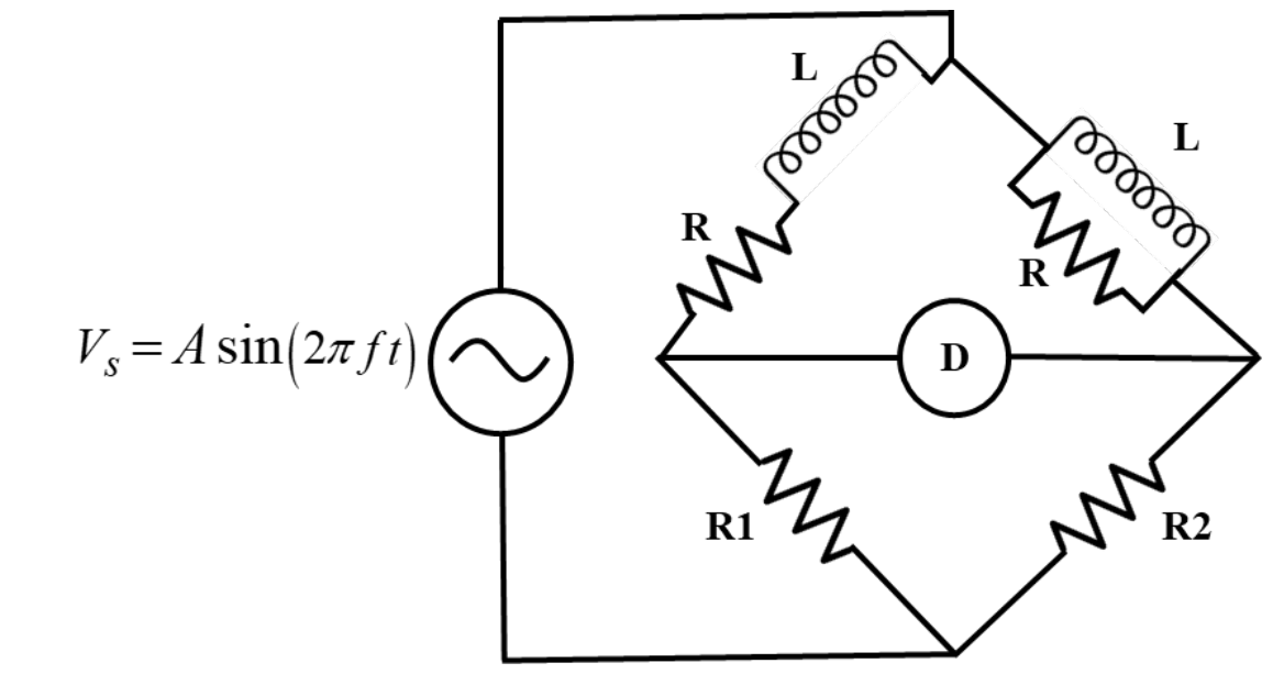
Consider an AC bridge shown in the figure with \(R = 300\ \Omega\), \(R1 = 1000\ \Omega\), \(R2 = 500\ \Omega\), \(L = 30\) mH, and a detector D. At the bridge balance condition, the frequency of the excitation source \(V_s\) is ____kHz (rounded off to two decimal places).

Source question diagram

Open complete paper
19
2025 · Instrumentation Engineering · Measurements · Bridges and Electrical Quantity Measurement
Instrumentation Engineering (IN) 2025
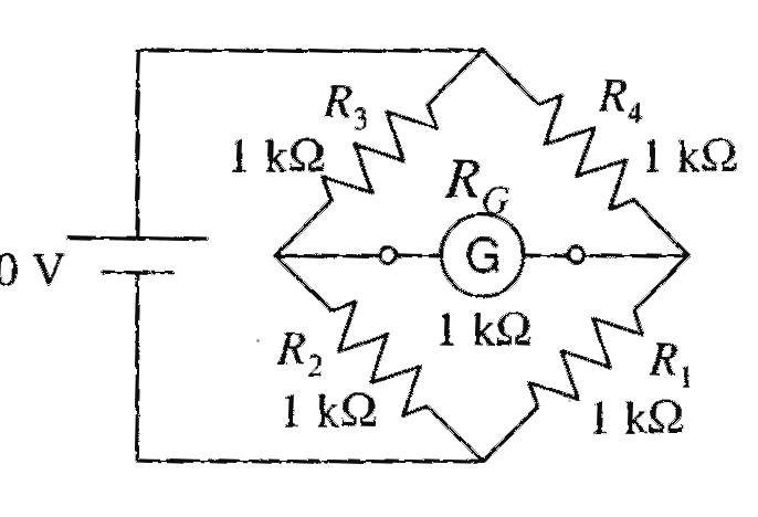
In the circuit shown, the galvanometer (G) has an internal resistance of 100 Ω. The galvanometer current IG is ______ μA (rounded off to the nearest integer).
Open complete paper
20
2007 · Instrumentation Engineering · Measurements · Bridges and Electrical Quantity Measurement
Instrumentation Engineering (IN) 2007
Consider the AC bridge shown in the figure below, with \(A\), \(L\) and \(C\) having positive finite values.

Then
Open complete paper

Showing 20 of 49 questions