My Cart
Your Cart 0

    Your cart is empty.

  • Total (Amount) ₹0.00
Previous year question hub

Operational Amplifiers and Signal Generators - Analog Electronics - Instrumentation Engineering Previous Year Questions

Practice Operational Amplifiers and Signal Generators - Analog Electronics - Instrumentation Engineering previous year questions organised from real papers, with year-wise coverage and clear topic navigation.

21Papers
18Years
119Questions
1Topics

Operational Amplifiers and Signal Generators question pattern

Every graph below is calculated only from this selection.

Questions by year

Year-wise coverage for Operational Amplifiers and Signal Generators. Each bar uses a separate theme-derived color.

Difficulty distribution

How the classified questions are distributed by difficulty.

Medium 95 79.8%
Easy 23 19.3%
Hard 1 0.8%
Question type distribution

MCQ, numerical, multiple-select and other formats found in these papers.

MCQ 73 61.3%
Numerical Answer Type (NAT) 30 25.2%
Fill in the blanks 11 9.2%
MSQ 5 4.2%

Subject weightage

Top subjects by unique question coverage.

Instrumentation Engineering
119 Qs

Most asked topics

Top topics across the included previous year papers.

Analog Electronics
119 Qs

Subtopic coverage

Top subtopics inside this exact selection.

Operational Amplifiers and Signal Generators
119 Qs

Paper coverage

Question coverage for the most populated papers. Every active PYP paper remains listed below.

Instrumentation Engineering (IN) 2026
4 Qs
Instrumentation Engineering (IN) 2025
5 Qs
Instrumentation Engineering (IN) 2024
6 Qs
Instrumentation Engineering (IN) 2023
4 Qs
Instrumentation Engineering (IN) 2022
5 Qs
Instrumentation Engineering (IN) 2021
3 Qs
Instrumentation Engineering (IN) 2020
4 Qs
Instrumentation Engineering (IN) 2019
5 Qs
Instrumentation Engineering (IN) 2018
5 Qs
Instrumentation Engineering (IN) 2017
8 Qs
Instrumentation Engineering (IN) 2016
5 Qs
Instrumentation Engineering (IN) 2014
5 Qs
Instrumentation Engineering (IN) 2013 [Session 2]
9 Qs
Instrumentation Engineering (IN) 2013 [Session 3]
8 Qs
Instrumentation Engineering (IN) 2013 [Session 4]
8 Qs
Instrumentation Engineering (IN) 2013 [Session 1]
3 Qs
Instrumentation Engineering (IN) 2011
5 Qs
Instrumentation Engineering (IN) 2010
5 Qs
Instrumentation Engineering (IN) 2009
5 Qs
Instrumentation Engineering (IN) 2008
6 Qs
Instrumentation Engineering (IN) 2007
11 Qs

Included previous year papers

Newest papers appear first. Sort by year, question coverage or name.

PaperYear / sessionQuestions in this viewOpen
Instrumentation Engineering (IN) 202620264View paper
Instrumentation Engineering (IN) 202520255View paper
Instrumentation Engineering (IN) 202420246View paper
Instrumentation Engineering (IN) 202320234View paper
Instrumentation Engineering (IN) 202220225View paper
Instrumentation Engineering (IN) 202120213View paper
Instrumentation Engineering (IN) 202020204View paper
Instrumentation Engineering (IN) 201920195View paper
Instrumentation Engineering (IN) 201820185View paper
Instrumentation Engineering (IN) 201720178View paper
Instrumentation Engineering (IN) 201620165View paper
Instrumentation Engineering (IN) 201420145View paper
Instrumentation Engineering (IN) 2013 [Session 1]20133View paper
Instrumentation Engineering (IN) 2013 [Session 2]20139View paper
Instrumentation Engineering (IN) 2013 [Session 3]20138View paper
Instrumentation Engineering (IN) 2013 [Session 4]20138View paper
Instrumentation Engineering (IN) 201120115View paper
Instrumentation Engineering (IN) 201020105View paper
Instrumentation Engineering (IN) 200920095View paper
Instrumentation Engineering (IN) 200820086View paper
Instrumentation Engineering (IN) 2007200711View paper

All Operational Amplifiers and Signal Generators previous year questions

Practice every matching question in batches of 20, with every available option.

1
2009 · Instrumentation Engineering · Analog Electronics · Operational Amplifiers and Signal Generators
Instrumentation Engineering (IN) 2009

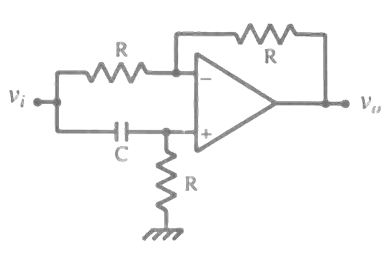
The circuit shown in the figure is

Open complete paper
2
2009 · Instrumentation Engineering · Analog Electronics · Operational Amplifiers and Signal Generators
Instrumentation Engineering (IN) 2009

The input resistance of the circuit shown in the figure, assuming an ideal op amp, is

Open complete paper
3
2009 · Instrumentation Engineering · Analog Electronics · Operational Amplifiers and Signal Generators
Instrumentation Engineering (IN) 2009
In the circuit shown in the figure, the switch S has been in Position 1 for a long time. It is then moved to Position 2. Assume the Zener diodes to be ideal. The time delay between the switch moving to Position 2 and the transition in the output voltage \(V_o\) is

Question diagram

Open complete paper
4
2009 · Instrumentation Engineering · Analog Electronics · Operational Amplifiers and Signal Generators
Instrumentation Engineering (IN) 2009
The circuit is used at a sampling rate of 1 kHz, with an A/D converter having a conversion time of 200 μs. The op amp has an input bias current of 10 nA. The maximum hold error is
Open complete paper
5
2009 · Instrumentation Engineering · Analog Electronics · Operational Amplifiers and Signal Generators
Instrumentation Engineering (IN) 2009
The small-signal voltage gain of the circuit is
Open complete paper
6
2010 · Instrumentation Engineering · Analog Electronics · Operational Amplifiers and Signal Generators
Instrumentation Engineering (IN) 2010
In the ideal opamp circuit given in the adjoining figure, the value of \( R_f \) is varied from 1 kΩ to 100 kΩ. The gain \( G = (v_o / v_i) \) will
Open complete paper
7
2010 · Instrumentation Engineering · Analog Electronics · Operational Amplifiers and Signal Generators
Instrumentation Engineering (IN) 2010
An active filter is shown in the adjoining figure. The dc gain and the 3 dB cut-off frequency of the filter respectively, are nearly
\(R_1 = 15.9 \text{ k}\Omega, R_2 = 159 \text{ k}\Omega\)
\(C_1 = 1.0 \text{ nF}\)
Open complete paper
8
2010 · Instrumentation Engineering · Analog Electronics · Operational Amplifiers and Signal Generators
Instrumentation Engineering (IN) 2010
The input impedances seen looking into the terminals \(V_1\) and \(V_2\) with respect to ground, respectively are
Open complete paper
9
2010 · Instrumentation Engineering · Analog Electronics · Operational Amplifiers and Signal Generators
Instrumentation Engineering (IN) 2010
\(V_1\) and \(V_2\) are connected to voltage sources having an open circuit output of +1 V each and internal resistances of 13 kΩ and 3 kΩ respectively. The output voltage \(V_o\) is
Open complete paper
10
2010 · Instrumentation Engineering · Analog Electronics · Operational Amplifiers and Signal Generators
Instrumentation Engineering (IN) 2010
The above PMMC meter is connected in the circuit shown in the adjoining figure. The opamp is ideal. The voltage \(v_i(t) = 1.0 \sin 314t\) V. Assuming the source impedance of \(v_i(t)\) to be zero, the ammeter will indicate a current of
Open complete paper
11
2011 · Instrumentation Engineering · Analog Electronics · Operational Amplifiers and Signal Generators
Instrumentation Engineering (IN) 2011
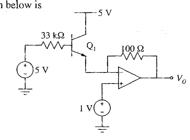
Assuming base-emitter voltage of 0.7 V and \(β = 99\) of transistor \(Q_1\), the output voltage \(V_O\) in the ideal opamp circuit shown below is
Open complete paper
12
2011 · Instrumentation Engineering · Analog Electronics · Operational Amplifiers and Signal Generators
Instrumentation Engineering (IN) 2011
Assuming zener diode \(D_1\) has current-voltage characteristics as shown below on the right and forward voltage drop of diode \(D_2\) is 0.7 V, the voltage \(V_O\) in the circuit shown below is
Open complete paper
13
2011 · Instrumentation Engineering · Analog Electronics · Operational Amplifiers and Signal Generators
Instrumentation Engineering (IN) 2011
The transfer characteristics of the circuit drawn below is observed on an oscilloscope used in XY mode. The display on the oscilloscope is shown on the right hand side. \(V_i\) is connected to the X input with a setting of 0.5 V/div, and \(V_o\) is connected to the Y input with a setting of 2 V/div. The beam is positioned at the origin when \(V_i\) is zero. Assuming that the opamp is ideal and the zener diodes have forward biased voltage drop of 0.7 V, the values of reverse break-down voltages of \(Z_1\) and \(Z_2\) are, respectively,
Open complete paper
14
2011 · Instrumentation Engineering · Analog Electronics · Operational Amplifiers and Signal Generators
Instrumentation Engineering (IN) 2011
The value of V₀ of the series regulator shown below is
Open complete paper
15
2011 · Instrumentation Engineering · Analog Electronics · Operational Amplifiers and Signal Generators
Instrumentation Engineering (IN) 2011
For the computed value of current Iₛ, the output voltage V₀ is
Open complete paper
16
2013 · Instrumentation Engineering · Analog Electronics · Operational Amplifiers and Signal Generators
Instrumentation Engineering (IN) 2013 [Session 1]
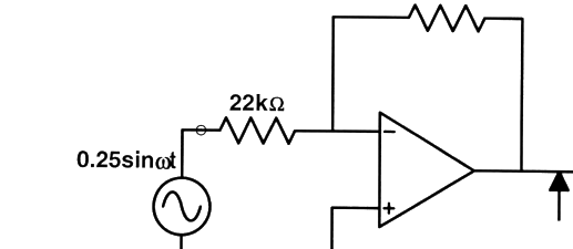
The operational amplifier shown in the circuit below has a slew rate of 0.8 Volts/μs. The input signal is \(0.25 \sin(\omega t)\). The maximum frequency of input in kHz for which there is no distortion in the output is

Question diagram

Open complete paper
17
2013 · Instrumentation Engineering · Analog Electronics · Operational Amplifiers and Signal Generators
Instrumentation Engineering (IN) 2013 [Session 1]

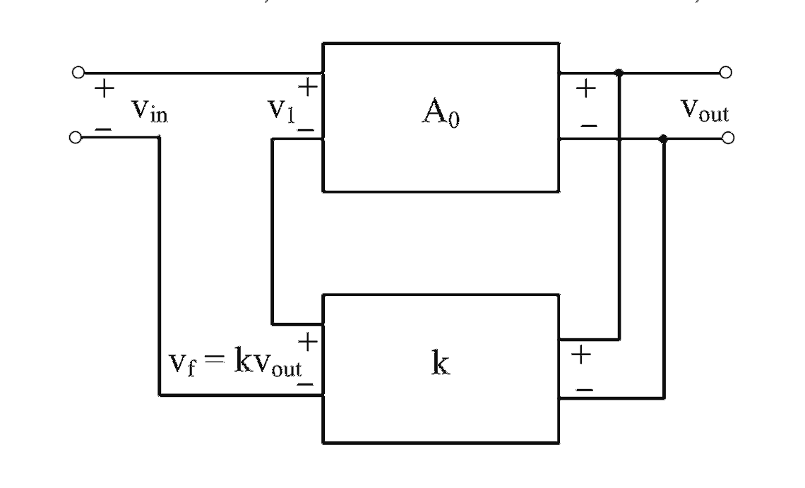
In the feedback network shown below, if the feedback factor k is increased, then the

Open complete paper
18
2013 · Instrumentation Engineering · Analog Electronics · Operational Amplifiers and Signal Generators
Instrumentation Engineering (IN) 2013 [Session 1]
Assuming its differential gain to be 10 and the op-amp to be otherwise ideal, the CMRR is

Question diagram

Open complete paper
19
2013 · Instrumentation Engineering · Analog Electronics · Operational Amplifiers and Signal Generators
Instrumentation Engineering (IN) 2013 [Session 2]
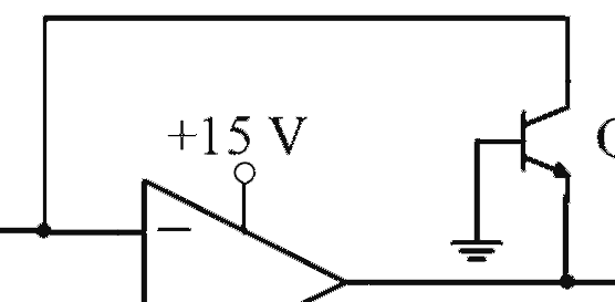
In the circuit shown below what is the output voltage \( V_{out} \) in Volts if a silicon transistor Q and an ideal op-amp are used?
Open complete paper
20
2013 · Instrumentation Engineering · Analog Electronics · Operational Amplifiers and Signal Generators
Instrumentation Engineering (IN) 2013 [Session 2]
In the feedback network shown below, if the feedback factor \( k \) is increased, then the

Question diagram

Open complete paper

Showing 20 of 111 questions