My Cart
Your Cart 0

    Your cart is empty.

  • Total (Amount) ₹0.00
Previous year question hub

Diodes and Transistor Amplifiers - Analog Electronics - Instrumentation Engineering Previous Year Questions

Practice Diodes and Transistor Amplifiers - Analog Electronics - Instrumentation Engineering previous year questions organised from real papers, with year-wise coverage and clear topic navigation.

21Papers
18Years
48Questions
1Topics

Diodes and Transistor Amplifiers question pattern

Every graph below is calculated only from this selection.

Questions by year

Year-wise coverage for Diodes and Transistor Amplifiers. Each bar uses a separate theme-derived color.

Difficulty distribution

How the classified questions are distributed by difficulty.

Medium 38 79.2%
Easy 8 16.7%
Hard 2 4.2%
Question type distribution

MCQ, numerical, multiple-select and other formats found in these papers.

MCQ 33 68.8%
Numerical Answer Type (NAT) 13 27.1%
Fill in the blanks 2 4.2%

Subject weightage

Top subjects by unique question coverage.

Instrumentation Engineering
48 Qs

Most asked topics

Top topics across the included previous year papers.

Analog Electronics
48 Qs

Subtopic coverage

Top subtopics inside this exact selection.

Diodes and Transistor Amplifiers
48 Qs

Paper coverage

Question coverage for the most populated papers. Every active PYP paper remains listed below.

Instrumentation Engineering (IN) 2026
2 Qs
Instrumentation Engineering (IN) 2025
1 Qs
Instrumentation Engineering (IN) 2024
1 Qs
Instrumentation Engineering (IN) 2023
2 Qs
Instrumentation Engineering (IN) 2022
4 Qs
Instrumentation Engineering (IN) 2021
2 Qs
Instrumentation Engineering (IN) 2020
2 Qs
Instrumentation Engineering (IN) 2019
3 Qs
Instrumentation Engineering (IN) 2018
1 Qs
Instrumentation Engineering (IN) 2017
2 Qs
Instrumentation Engineering (IN) 2016
1 Qs
Instrumentation Engineering (IN) 2014
3 Qs
Instrumentation Engineering (IN) 2013 [Session 4]
4 Qs
Instrumentation Engineering (IN) 2013 [Session 1]
3 Qs
Instrumentation Engineering (IN) 2013 [Session 2]
3 Qs
Instrumentation Engineering (IN) 2013 [Session 3]
3 Qs
Instrumentation Engineering (IN) 2011
1 Qs
Instrumentation Engineering (IN) 2010
1 Qs
Instrumentation Engineering (IN) 2009
3 Qs
Instrumentation Engineering (IN) 2008
3 Qs
Instrumentation Engineering (IN) 2007
3 Qs

Included previous year papers

Newest papers appear first. Sort by year, question coverage or name.

PaperYear / sessionQuestions in this viewOpen
Instrumentation Engineering (IN) 202620262View paper
Instrumentation Engineering (IN) 202520251View paper
Instrumentation Engineering (IN) 202420241View paper
Instrumentation Engineering (IN) 202320232View paper
Instrumentation Engineering (IN) 202220224View paper
Instrumentation Engineering (IN) 202120212View paper
Instrumentation Engineering (IN) 202020202View paper
Instrumentation Engineering (IN) 201920193View paper
Instrumentation Engineering (IN) 201820181View paper
Instrumentation Engineering (IN) 201720172View paper
Instrumentation Engineering (IN) 201620161View paper
Instrumentation Engineering (IN) 201420143View paper
Instrumentation Engineering (IN) 2013 [Session 1]20133View paper
Instrumentation Engineering (IN) 2013 [Session 2]20133View paper
Instrumentation Engineering (IN) 2013 [Session 3]20133View paper
Instrumentation Engineering (IN) 2013 [Session 4]20134View paper
Instrumentation Engineering (IN) 201120111View paper
Instrumentation Engineering (IN) 201020101View paper
Instrumentation Engineering (IN) 200920093View paper
Instrumentation Engineering (IN) 200820083View paper
Instrumentation Engineering (IN) 200720073View paper

All Diodes and Transistor Amplifiers previous year questions

Practice every matching question in batches of 20, with every available option.

1
2009 · Instrumentation Engineering · Analog Electronics · Diodes and Transistor Amplifiers
Instrumentation Engineering (IN) 2009
In the circuit shown, the Zener diode has ideal characteristics and a breakdown voltage of 3.2 V. The output voltage \(V_o\) for an input voltage \(V_i = +1\) V is closest to
Open complete paper
2
2009 · Instrumentation Engineering · Analog Electronics · Diodes and Transistor Amplifiers
Instrumentation Engineering (IN) 2009
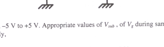
Common Data for Questions 51 and 52 : The figure shows a sample-and-hold circuit using a MOSFET as a switch. The threshold voltage of the MOSFET is +2 V. It has zero leakage current in the off state. Assume that the capacitor is ideal. The input voltage \(V_i\) ranges from -5 V to +5 V. Appropriate values of \(V_{sub}\), of \(V_g\) during sampling, and of \(V_g\) during hold are, respectively,

Question diagram

Open complete paper
3
2009 · Instrumentation Engineering · Analog Electronics · Diodes and Transistor Amplifiers
Instrumentation Engineering (IN) 2009
The bias voltage \(V_B\) at the base of the transistor \(Q_3\) is approximately

Question diagram

Open complete paper
4
2010 · Instrumentation Engineering · Analog Electronics · Diodes and Transistor Amplifiers
Instrumentation Engineering (IN) 2010
The matched transistors Q1 and Q2 shown in the adjoining figure have \(\beta = 100\). Assuming the base-emitter voltages to be 0.7 V, the collector-emitter voltage \(V_2\) of the transistor Q2 is
Open complete paper
5
2011 · Instrumentation Engineering · Analog Electronics · Diodes and Transistor Amplifiers
Instrumentation Engineering (IN) 2011
The amplifier shown below has a voltage gain of \(-2.5\), an input resistance of \(10\ k\Omega\) and a lower 3-dB cut-off frequency of \(20\ Hz\). Which one of the following statements is TRUE when the emitter resistance \(R_E\) is doubled?
Open complete paper
6
2013 · Instrumentation Engineering · Analog Electronics · Diodes and Transistor Amplifiers
Instrumentation Engineering (IN) 2013 [Session 1]
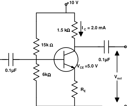
In the transistor circuit as shown below, the value of resistance \(R_E\) in kΩ is approximately.

Question diagram

Open complete paper
7
2013 · Instrumentation Engineering · Analog Electronics · Diodes and Transistor Amplifiers
Instrumentation Engineering (IN) 2013 [Session 1]
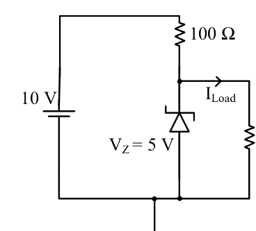
For the circuit shown below, the knee current of the ideal Zener diode is 10 mA. To maintain 5 V across \(R_L\), the minimum value of the load resistor \(R_L\) in \(\Omega\) and the minimum power rating of the Zener diode in mW, respectively, are
Open complete paper
8
2013 · Instrumentation Engineering · Analog Electronics · Diodes and Transistor Amplifiers
Instrumentation Engineering (IN) 2013 [Session 1]
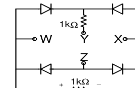
A voltage \(1000\sin \omega t\) Volts is applied across YZ. Assuming ideal diodes, the voltage measured across WX in Volts, is
Open complete paper
9
2013 · Instrumentation Engineering · Analog Electronics · Diodes and Transistor Amplifiers
Instrumentation Engineering (IN) 2013 [Session 2]
In the transistor circuit as shown below, the value of resistance \( R_E \) in kΩ is approximately,
Open complete paper
10
2013 · Instrumentation Engineering · Analog Electronics · Diodes and Transistor Amplifiers
Instrumentation Engineering (IN) 2013 [Session 2]
A voltage $1000\sin \omega t$ Volts is applied across YZ. Assuming ideal diodes, the voltage measured across WX in Volts, is

Question diagram

Open complete paper
11
2013 · Instrumentation Engineering · Analog Electronics · Diodes and Transistor Amplifiers
Instrumentation Engineering (IN) 2013 [Session 2]
For the circuit shown below, the knee current of the ideal Zener diode is 10 mA. To maintain 5 V across \( R_L \), the minimum value of the load resistor \( R_L \) in \( \Omega \) and the minimum power rating of the Zener diode in mW, respectively, are
Open complete paper
12
2013 · Instrumentation Engineering · Analog Electronics · Diodes and Transistor Amplifiers
Instrumentation Engineering (IN) 2013 [Session 3]
In the transistor circuit as shown below, the value of resistance RE in kΩ is approximately.
Open complete paper
13
2013 · Instrumentation Engineering · Analog Electronics · Diodes and Transistor Amplifiers
Instrumentation Engineering (IN) 2013 [Session 3]
For the circuit shown below, the knee current of the ideal Zener diode is 10 mA. To maintain 5 V across R_L, the minimum value of the load resistor R_L in Ω and the minimum power rating of the Zener diode in mW, respectively, are

Question diagram

Open complete paper
14
2013 · Instrumentation Engineering · Analog Electronics · Diodes and Transistor Amplifiers
Instrumentation Engineering (IN) 2013 [Session 3]
A voltage 1000 sin ωt Volts is applied across YZ. Assuming ideal diodes, the voltage measured across WX in Volts, is
Open complete paper
15
2013 · Instrumentation Engineering · Analog Electronics · Diodes and Transistor Amplifiers
Instrumentation Engineering (IN) 2013 [Session 4]
In the transistor circuit as shown below, the value of resistance \( R_E \) in k\( \Omega \) is approximately,
Open complete paper
16
2013 · Instrumentation Engineering · Analog Electronics · Diodes and Transistor Amplifiers
Instrumentation Engineering (IN) 2013 [Session 4]
The circuit below incorporates a permanent magnet moving coil milli-ammeter of range 1 mA having a series resistance of 10 k$\Omega$. Assuming constant diode forward resistance of 50 $\Omega$, a forward diode drop of 0.7 V and infinite reverse diode resistance for each diode, the reading of the meter in mA is
Open complete paper
17
2013 · Instrumentation Engineering · Analog Electronics · Diodes and Transistor Amplifiers
Instrumentation Engineering (IN) 2013 [Session 4]
A voltage 1000 $\sin \omega t$ Volts is applied across YZ. Assuming ideal diodes, the voltage measured across WX in Volts, is
Open complete paper
18
2014 · Instrumentation Engineering · Analog Electronics · Diodes and Transistor Amplifiers
Instrumentation Engineering (IN) 2014
For the circuit shown in the figure assume ideal diodes with zero forward resistance and zero forward voltage drop. The current through the diode \(D_2\) in mA is ______________.
Open complete paper
19
2014 · Instrumentation Engineering · Analog Electronics · Diodes and Transistor Amplifiers
Instrumentation Engineering (IN) 2014
For the circuit shown in the figure, the transistor has β = 40, \( V_{BE} = 0.7 \) V, and the voltage across the Zener diode is 15 V. The current (in mA) through the Zener diode is ______________.
Open complete paper
20
2014 · Instrumentation Engineering · Analog Electronics · Diodes and Transistor Amplifiers
Instrumentation Engineering (IN) 2014
In the figure, transistors \( T_1 \) and \( T_2 \) have identical characteristics. \( V_{CE(sat)} \) of transistor \( T_1 \) is 0.1 V. The voltage \( V_1 \) is high enough to put \( T_1 \) in saturation. Voltage \( V_{BE} \) of transistors \( T_1, T_2 \) and \( T_3 \) is 0.7 V. The value of \( (V_1 - V_2) \) in V is ______________.
Open complete paper

Showing 20 of 47 questions